Engine Balance
ENGINE BALANCE
DALE HERBRANDSON
Dale Herbrandson, BSME, works in the Advanced Design Division of the McCulloch Corporation and has the enviable task of performing development test programs on all manner of exotic engine designs. He's more than a theoretician, however; he has ridden and worked with motorcycles for some years and prefers to prove his work with operating hardware—to the extent of building his own engines from the ground up. Rarely, if ever, is he without a personal construction project.
THERE ARE MANY FORCES present in a simple, single-cylinder engine. The one that makes the engine run is produced by the pressure in the combustion chamber acting on the piston area. This force is divided many ways while being transferred through the workings of the engine. Losses include friction from piston side thrust, ring friction, piston and connecting rod inertia, crankcase pressure, bearing friction, etc.
After all this, there are only two reactions felt external to the engine. The first is the output torque, the second is the unwelcome inertia load from the piston and connecting rod. These inertia loads and their effect is the subject of this article.
As long as an engine has components that reciprocate, there will be shaking forces present. As they cannot be eliminated, the idea behind engine balancing is to reduce these forces with opposing forces.
These opposing forces may come from an imbalance on the crankshaft, external balancing weights, or by another cylinder on the same engine.
The majority of motorcycles on the road today have a high degree of inherent engine imbalance. In addition to being felt as a motorcycle is ridden, imbalance shows up eventually as mechanical failure. Parts break from fatigue, nuts and bolts come loose, and all the while the operator suffers. This cannot be attributed to poor workmanship on the part of the manufacturer, because an engine continues to shake even after it has been expertly balanced.
Many articles have been written on how to balance an engine, and in the main, their advice is sound. If followed correctly, these widely accepted procedures will do much to reduce the shake with which we are all too familiar.
But, have you ever wondered what the basic principles are behind this work? Why are most designs just a compromise? And just how high are the magnitudes of these unbalanced forces? The answers to these questions lie in the geometry of the basic engine components.
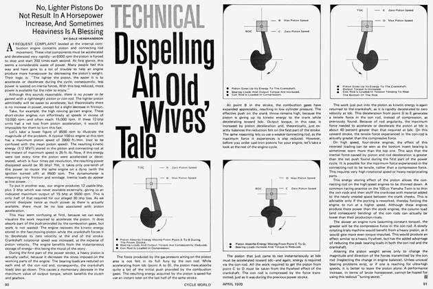
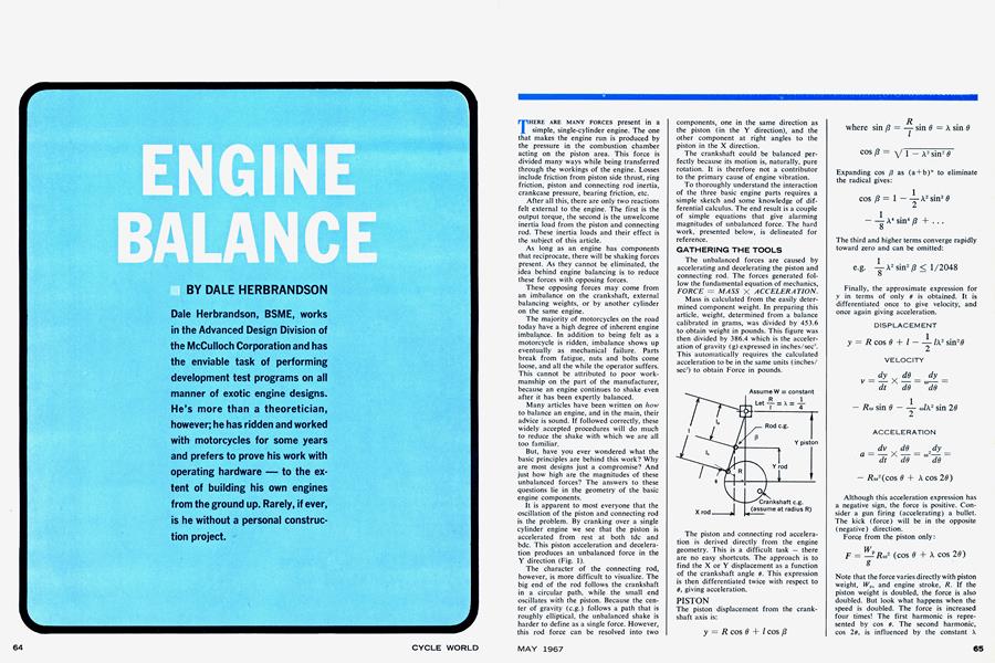
It is apparent to most everyone that the oscillation of the piston and connecting rod is the problem. By cranking over a single cylinder engine we see that the piston is accelerated from rest at both tdc and bdc. This piston acceleration and deceleration produces an unbalanced force in the Y direction (Fig. 1).
The character of the connecting rod, however, is more difficult to visualize. The big end of the rod follows the crankshaft in a circular path, while the small end oscillates with the piston. Because the center of gravity (e.g.) follows a path that is roughly elliptical, the unbalanced shake is harder to define as a single force. However, this rod force can be resolved into two
components, one in the same direction as the piston (in the Y direction), and the other component at right angles to the piston in the X direction.
The crankshaft could be balanced perfectly because its motion is, naturally, pure rotation. It is therefore not a contributor to the primary cause of engine vibration.
To thoroughly understand the interaction of the three basic engine parts requires a simple sketch and some knowledge of differential calculus. The end result is a couple of simple equations that give alarming magnitudes of unbalanced force. The hard work, presented below, is delineated for reference.
GATHERING THE TOOLS
The unbalanced forces are caused by accelerating and decelerating the piston and connecting rod. The forces generated follow the fundamental equation of mechanics, FORCE = MASS X ACCELERATION.
Mass is calculated from the easily determined component weight. In preparing this article, weight, determined from a balance calibrated in grams, was divided by 453.6 to obtain weight in pounds. This figure was then divided by 386.4 which is the acceleration of gravity (g) expressed in inches/sec". This automatically requires the calculated acceleration to be in the same units (inches/ sec") to obtain Force in pounds.
The piston and connecting rod acceleration is derived directly from the engine geometry. This is a difficult task — there are no easy shortcuts. The approach is to find the X or Y displacement as a function of the crankshaft angle d. This expression is then differentiated twice with respect to d, giving acceleration.
PISTON
The piston displacement from the crankshaft axis is:
Expanding cos ß as (a + b)n to eliminate the radical gives:
The third and higher terms converge rapidly toward zero and can be omitted:
Finally, the approximate expression for y in terms of only e is obtained. It is differentiated once to give velocity, and once again giving acceleration.
DISPLACEMENT
VELOCITY
ACCELERATION
Although this acceleration expression has a negative sign, the force is positive. Consider a gun firing (accelerating) a bullet. The kick (force) will be in the opposite (negative) direction.
Force from the piston only:
Note that the force varies directly with piston weight, Wp, and engine stroke, R. If the piston weight is doubled, the force is also doubled. But look what happens when the speed is doubled. The force is increased four times! The first harmonic is represented by cos 6. The second harmonic, cos 2d, is influenced by the constant X
which is R/l. As we would expect, the second harmonic is reduced when the rod length / is increased. At tdc the harmonics add, at bdc they subtract.
PISTON VELOCITY
If the connecting rod were made extremely long compared to the engine stroke in a hypothetical engine, the piston speed would be easy to describe. In the equation
term approaches zero, leaving only the first harmonic, which is unchanged. The resulting Simple Harmonic Motion gives a symmetrical pattern to piston motion on the first and last halves of the stroke. Starting from rest at tdc, piston speed increases until the maximum velocity is reached halfway through the stroke when 6 equals 90 degrees. The other half of the stroke is a mirror image of the first. The change in displacement or velocity on the last half of the stroke, say from 160 to 170 degrees, is of the same magnitude as that from 10 to 20 degrees on the first half. Equal time is required for each half of the stroke; however, this is not the case for the conventional engine.
When a finite length is used for the connecting rod, the situation becomes more complex. The velocity is then represented by both harmonics. They add on the first half of the stroke and subtract on the last half.
Before going any further, the actual velocity profile should be examined in an engine. Using the measurements of a working-model engine (BSA Goldstar 500cc):
we find the velocity profile as shown below. These values must be calculated as there is no way to get this information in a "bench test" arrangement.
The maximum velocity occurs at 76 degrees after tdc and not at the expected 90 degrees. Even if the rod length were doubled, Vmax would occur at 82 degrees after tdc.
The chart points out one important effect of rod angularity. The time required to accelerate the piston to maximum speed from tdc is less than that needed to slow it to a stop again at bdc. Yes, we are assuming constant engine rpm.
For example, the velocity increase from 10 to 20 degrees is 1,130 feet per minute. From 160 to 170 degrees, which is an equivalent part of the tail end of the stroke, this change is only 705 ft/min. This explains why the engine shakes harder at tdc than toward the end of the stroke. During the first half of the stroke, the time allowed to give the piston its maximum speed is relatively short. The force must be correspondingly high over the 76 degree period. The last half of the stroke has about 25 percent more time because of its 104-degree duration. By spreading out the exertion over a longer time, the last half of the stroke requires a smaller average force.
Two-stroke designers find this time difference a blessing, because it allows more time during the blow-down and transfer stages of the cycle, as they occur when the piston is in the region of bdc.
Notice that the chart is plotted with instantaneous velocity. It has a maximum value of 5,650 ft/min. This should not be confused with the mean piston speed, often used as a measure of engine reliability. For the BSA the mean speed is 3,460 ft/min. at 6,000 rpm.
CRANKSHAFT
The crankshaft counterweight produces a single radial force which is easily separated into X and Y components. Note that the angle to the counterweight e.g. is not 6, but 6 + 180 degrees.
RADIAL FORCE COMPONENT
VERTICAL FORCE COMPONENT
HORIZONTAL FORCE COMPONENT
CONNECTING ROD
The connecting rod has a displacement in both the X and Y directions. Two force components are therefore present. Starting with X
DISPLACEMENT
VELOCITY
ACCELERATION
The calculated force in the X direction is :
Notice that this force resembles the crankshaft imbalance in the X direction, except that the value here is positive. Again, from the sketch, the Y displacement is:
DISPLACEMENT
VELOCITY
ACCELERATION
The vertical force from only the connecting rod is:
COMBINED EFFECTS OF PISTON AND ROD
Something very interesting happens when the equation above for vertical rod force is written in another form.
Notice that the first portion of the equa tion resembles the equation for the piston unbalanced force. The second half of the equation resembles the crankshaft vertical force component. This is precisely what allows us to shuffle the rod effects around.
The weight of the big end of the rod,
which is easily determined on the beam balance, is assumed concentrated at the crankshaft throw. The lighter small end,
is assumed concentrated at the piston~
SIMPLIFIED ENGINE MODEL
The engine can be quite accurately repre sented by the following mathematical model. It assumes a weightless connecting rod. The new piston weight is heavier than
the actual by
The crankshaft weight
is increased by adding
to the throw,
opposite the counterweight.
To balance this engine we proceed in two steps. First, the rotating imbalance is taken care of by increasing the counterweight to
compensate for
added to the throw.
This leaves the oscillating piston to deal with. It is balanced by choosing a certain percent of the reciprocating weight, assumed at the piston as outlined later.
APPLYING THE TOOLS
By now, you're probably ready to turn the page and forget about the whole thing. We can, however, use the results of the above discussion without getting too in volved. Probably the best way to under stand the why behind balancing would be to use a practical example that would allow the painful symbols to be replaced by famil iar numbers which will represent pounds of force. The required input information, used in the equations, are length and weight.
SINGLE-CYLINDER ENGINES
As a working model, the single-cylinder, 500cc, BSA Gold Star engine produced some interesting values, and we thank Le Bard & Underwood, in La Habra, Calif., for providing the difficuli-to-find BSA parts. Using the beam balance again, we find that the piston with wrist pin and rings weighs 460 grams. The connecting rod (without big-end bearing) tips the scale at 552 grams. We had some trouble in obtaining the weights of the big end and small end of the rod. Fortunately, the two quantities are easily calculated, knowing the location of the rod c.g. The rod was balanced on a pencil - the c.g. is naturally at the point of balance. The distance (la) from the big end cent& to the c.g. measures 1.80 inch on the 6.50 inch long connecting rod. One half of the 88mm stroke expressed in inches is 1.732.
All of the required parameters for this engine are then:
PISTON WEIGHT . Wp ROD WEIGHT Wr ROD LENGTH 1 ROD BIG END TOC.G ROD SMALL END TOC.G 1/z OF STROKE R ARBITRARY SPEED N = 460 GRAMS = 552 GRAMS = 6.50 INCHES = 1.80 INCHES = 4.70 INCHES 1.73 INCHES = 6.000 RPM
By now we know that the piston and rod are the heart of the problem, so let's start with these and see what the basic imbalance is. Later, the approach can be expanded in an attempt to balance the BSA. To start out, let's assume that the crankshaft (with big end bearing in place) is perfectly bal anced. This way, only the effect of the piston and rod will be felt, but remember, these two parts produce forces in both the X and Y directions.
The single radial force (FR) is produced by the crankshaft counterweight.
Mathematically FR can be separated into two handy components. It is easier to treat the engine as a unit sharing in only the X and Y directions.
The discussion of the mathematical tools tells us that only two factors influence the imbalance produced by the piston. One is its weight, the other is the acceleration re quired to yank the piston from rest to a high speed and then slow it to a stop again. This is a difficult task, because when the BSA is turning at 6,000 rpm, the piston velocity varies from zero at tdc and bdc, to a maximum of 62 mph roughly half way through the stroke. This starting and stop ping occurs twice per revolution or 200 times per second. This gives "0-60" time for the piston of two thousandths of a second.
The forces involved are surprisingly high. At tdc, over one ton of force is required to start the piston on its way. This imbal ance is found from the product of piston mass and its acceleration. Referring back to the mathematical tools, the expression for acceleration is:
Because of connecting rod angularity, the acceleration is composed of two trigono metric terms - a first and a second har monic. At tdc the two add, giving an acceleration figure of 72,200 ft/sec2. At bdc, the harmonics subtract, resulting in a reduced acceleration of 41,800 ft/sec2. The racing industry has found an upper limit for acceleration to be in the neighborhood of 100,000 ft/sec2.
The calculated shaking force at the speed of 6,000 rpm is found to be:
At tdc, these add giving a total of 2,280 pounds.
To carry this point a bit further, let's increase the engine speed to 7,000 rpm. The acceleration, increasing with the square of rpm, is 98,500 ft/sec2. At tdc, 3,100 pounds of force is required to accelerate just the piston. Let's see what is required by the connecting rod.
The connecting rod forces are found in the same manner as the piston forces. In the Y direction two harmonics are again present. Their calculated value is: Fy — 2,143 cos ff + 156 cos 2ff Notice that the maximum value of 2,300 pounds is greater than our previous piston imbalance. The rod in this particular engine produces more vertical imbalance than does the piston.
The rod generates another imbalance, in the X direction, as it is moved from one side of the crankcase to the other. This is easily calculated as only a first harmonic is present. At 6,000 rpm the value is: Fx = 1,560 sin ff The effects of the piston and rod are additive. In the Y direction, the maximum value occurs at tdc. Their combined effect produces a whopping 4,580 pounds of unbalanced force.
As there are no X direction effects from the piston, our total comes from the rod alone. As shown above this value is 1,560 pounds.
These basic inertia forces are always present in the engine, and can only be reduced by decreasing the weight of the piston or rod, or by running the engine at a slower speed.
Fortunately, the full effect of these forces is not felt external to the engine. They are opposed internally by imbalance designed into the crankshaft counterweight. The sum of these opposing forces gives us the total effect of engine balance.
Our mathematical approach tells us three things to consider when designing the crankshaft:
1. The horizontal effect (1,560 pounds) from the connecting rod can be completely balanced by the crankshaft counterweight. The crank weight, with its e.g. assumed at radius R, must be
/c
equal to W7,-—. This is the weight of the
big end of the rod (400 grams for the BSA). In our example, this 400 grams is in addition to the weight required to give the crank its initial balance. Remember that we left the big end bearing in place on the crank throw.
2. The first harmonic in the Y direction (3,943 pounds for the BSA) can be eliminated throughout the speed range. This requires a crank imbalance of Wv + Wv ( 1,012 grams).
3. The second harmonic in the Y direction
cannot be altered without resorting to additional balancing hardware, such as a pair of balancing weights, rotating at twice crankshaft speed. The inherent imbalance will therefore remain unaltered in the conventional engine. Obviously, the crankshaft counterweight cannot satisfy both the requirements of items 1 and 2, so a compromise must be made. However, we can be sure that the weight will be at least 400 grams, but not more than 1,012 grams for the BSA. The term "percent balance" is useful when making this compromise.
The designed imbalance on the crankshaft consists of:
• all of the rod weight assumed at the
crankshaft Wr—, plus
• a certain percent (percent balance)
of the reciprocating weight WV+WT— assumed at the piston.
The table shows the effect the crankshaft can have on total engine balance. Values range from too little to too much counterweight.
Notice that there is no magical point of optimum balance. There will always be an unbalanced force in excess of 1,000 pounds present in the BSA. This is a problem found in all single - cylinder machines — they simply cannot be perfectly balanced.
A big improvement was made at 0 percent balance. Both horizontal and vertical shake is reduced. Increasing the crankshaft counterbalance above this point causes one perplexing problem. To decrease the Y direction shake, the X direction imbalance must increase. The engine application determines the exact percentage used.
In a chain saw engine, for example, the crankshaft is weighted to only about 18 percent balance. Because these engines are laid down horizontally, the unbalanced force from the piston is bucked by the log being cut. At right angles to this, the shake is low as the rod force is balanced internally by the crankshaft. However, if this same engine were to be used in a go-cart the percent balance should be increased to about 65
percent. To give a reasonable balance, the X and Y force components should be about equal.
Getting back to Table 1 and the BSA, we find that a figure of 60 percent produces a good compromise. The 766-gram counterweight produces a 2,990-pound force which reduces the original 4,580-pound vertical force to 1,590 pounds. This same 2,990-pound force opposes the original 1,560-pound rod force, producing a net shake of 1,430 pounds in the opposite direction. And this, thumper fans, is about the best we can do for the BSA.
Some manufacturers find that the horizontal shake (parallel to the highway) is less annoying than the vertical component, and will therefore increase the balance figure to around 80 percent. In this manner they are increasing the imbalance in a direction that is not annoying to the operator. With a decrease in the bothersome vertical components, the overall balance (according to the rider, anyway) has improved. This same effect comes from a horizontal engine using only a 40 percent balance.
The equations tell us that engine vibration is always present — from idle to maximum speed. Theoretically, there is no speed that produces perfect engine balance. Yet, at times, the motorcycle as a unit seems perfectly free from vibration. The interaction of the somewhat flexible frame and the engine produces this effect.
TWO-CYLINDER ENGINES
The "long-legged" BSA Gold Star with its undersquare bore/stroke ratio is obsolete by today's standards. On the showroom floor it has been replaced by an oversquare vertical twin. We know how the twin performs power-wise. But from the standpoint of balance, the comparison is not so obvious.
For our "twin" example a 500cc Triumph was selected. The calculated shaking force from this engine will be essentially the same as that found in a BSA twin. This oversquare engine satisfies the requirements nicely with a 69.0mm bore and a 65.5mm stroke.
To obtain an even firing order, this vertical twin design requires that the pistons move up and down together. Balance wise, this is the worst possible arrangement. The shaking effects from each lung add. Consequently, the twin balances just like a single. The engine parameters from the Triumph are:
(Continued on page 119)
Notice that both pistons at 532 grams weigh more than the one used in the BSA Gold Star. The same is true of the connecting rods. Total reciprocating weight is greater. But, because of its shorter stroke, the twin is more highly balanced.
At 6,000 rpm the basic vertical imbalance from half of the twin is 1763 cos <9+197 cos 2d. The sum of both harmonics from both cylinders at tdc is 3,920 pounds. This is considerably less than the 4,580 pounds of the Gold Star.
Because this twin behaves just like a single, the same compromises between horizontal and vertical shake must be made. Using the 60 percent figure already obtained, we find the balanced twin producing a total Y direction imbalance of 770 cos 9 + 394 cos 2(9 pounds. In the X direction, the maximum force is 1,150 pounds.
At tdc, when the imbalance is greatest, the twin produces 1,164 pounds of shake — 37 percent less than the 1,590 pounds produced by the Gold Star.
To achieve this 60 percent balance figure, considerable weight must be added to the crankshaft counterweight. The required 950 grams must have its e.g. at the short radius of 1.09 inch from the crank center line.
Compare these figures to the undersquare single and you will find that more weight must be crowded into a smaller space. This could become quite a problem if the bore/ stroke ratio were further increased.
Both the single-cylinder and the twincylinder arrangements just described offer the worst possible balance arrangement. A relatively high degree of balance can be achieved by designing the cylinder arrangement so that the basic imbalance from each piston and connecting rod tend to cancel.
Let's take the 500cc Triumph set up with one piston at tdc and the other at bdc. Neglecting the effect this has on the firing order, it has a marvelous effect on the balance. The acceleration forces tend to cancel as the pistons move in opposite directions. The net force is not zero, however.
The force from the piston and rod positioned at tdc is:
At bdc, where the crank angle is 6 + 180°, the other piston and rod produce:
Summing the effects from both cylinders, we find that the first harmonics cancel and the second harmonics add. The resulting vertical imbalance of 394 pounds is obtained without help from the crankshaft counterweight. The horizontal components of each rod are represented by only a first harmonic, and quite nicely, their sum is zero. This redesigned unit now has only 10 percent of the original vertical imbalance, and none of the horizontal.
True to nature, this modified configuration introduces new complications. One half of the engine tends to lift, while the other tries to move down. Because these forces are separated by the cylinder spac-
ing, the machine now tends to rock from side to side. This rocking couple can be reduced by a pair of weights on our old standby, the crankshaft. The crankshaft can only reduce this rocking tendency, as a 100-percent reduction in the vertical direction results in a 100-percent increase in the horizontal. So again, a compromise must be made.
It is interesting to note that Honda uses this 180-degree crankshaft arrangement on their high output scrambler. This accounts for the uneven firing order, and reduced vibration. By coupling two of these twins together into an in-line four, the rocking couples can be eliminated. The resulting engine has all of its reciprocating machinery inherently balanced, with the exception of the second harmonic. The shaking effect from all four cylinders add.
As you can appreciate, this evaluation can continue almost without end. Engine balance can be improved only with increased complexity in the design. There will never be a smooth running single, or an uncomplicated four. There is one thing for sure; at least two cylinders are required for a reasonable degree of balance.
Once the origin of these acceleration forces for the single-cylinder engine are understood, a twoor threeor sixteencylinder machine is within our grasp. The basic ideas are here for your inquisition. ■