Improving Off-Road Lighting
IMPROVING OFF-ROAD LIGHTING
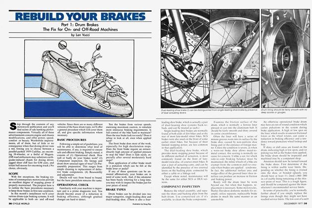
Project PE250 gets lights for night racing or just finding its way home
Len Vucci
Virtually all late-model off-road bikes suffer from a common congenital defect: dim-lightedness. Every enduro-style motorcycle to pass through here lately has been ill-equipped for night use.
This is not to say the lighting systems are inferior or sub-standard. All would get you through tech inspection at an event requiring full lighting. And for the majority of owners, this is probably the greatest demand to be placed upon the system.
But what does one do when forced to rely on enduro-type lights for night riding? One rides very slowly, and wishes the lights were brighter. The headlight on the typical enduro-equipped off-roader is rated at 15 watts. For comparison, a pair of Christmas tree bulbs produces an equivalent amount of light.
But you do not have to settle for such inadequate lighting. At your disposal is a generator, the magneto, capable of powering real headlights. All you have to do is tap that source in the proper manner, and bolt on the lights of your choice.
HEADLIGHT SWAPPING
Because of the nature of the beast, the magneto is very choosy when one attempts to present it with headlamps of different ratings. The magneto on a Suzuki PE250 powers a 6-volt, 15-watt bulb. Install a 6volt, 35-watt bulb and light output is doubled, right? Wrong. The “brighter” bulb will load down the stock coils, and most likely seem dimmer, even though the coils are working just as hard.
One would think the installation of a 12volt bulb would also load down the system. Not necessarily so. The stock PE coil will provide almost eight volts when an automotive sealed beam is connected. In terms of power, that’s about 25 watts.
Connect the same 12-volt sealed beam to a Yamaha TT500, and it will act like a flashbulb. It provides less of a load than the system was designed for, and allows the voltage to reach nearly 20 volts, and expires.
In short, the easy way won’t work. You can’t fit a bulb with a higher rating or fit a light from another model, because the light can only be as strong as the power source behind it.
What you can do—or have done, if you wish and can find an expert—is modify the stock magneto so it will produce enough power for a better light.
This article is one example. The subject is a Suzuki PE250. chosen because it’s our long-term competition bike. It has competed in races at night so it’s been fitted with all the lights it will carry.
The principles involved here will be basically the same for many other makes and models. The details will vary. They will vary a lot. Unless you're already experienced in electrical matters, don't use this article as the basis for reworking your Yamaha DT lights at home. Instead, we plan to do similar articles on other models, as demand warrants.
HEADLIGHT CHARACTERISTICS
Using one of several methods, you can modify your stock magneto so it will power either quartz-halogen lights rated at 12 volts, 55 watts, or automotive sealed beams, which are electrically similar. Each bulb type has its own advantages and disadvantages.
Quartz lights are brighter, and are available in a wide assortment of reflector configurations and beam patterns. The actual bulb is small, so a spare is easily carried. Prices vary, but figure on spending $25 for the complete assembly, and another $10 for a spare bulb.
Sealed beams are fairly bright, and have an acceptable pattern. Carrying a spare is a bit cumbersome, but a couple of bucks can get you one almost anywhere. Dual-filament (high/low beam) sealed beams are, in effect, their own spares. Or, if you convert the magneto to a dual system, both elements can be lit simultaneously. With an output over 100 watts, it’s literally a two-for-the-price-of-one deal.
DESCRIPTION OF MODIFICATIONS
Depending on the number of lights you wish to power (two is max.) and the amount of time and energy you wish to expend, there are four methods to use. Degree of difficulty varies from almost none to only slight. If you have access to a soldering iron, costs will range from zero to about two bucks, excluding the actual headlight, of course.
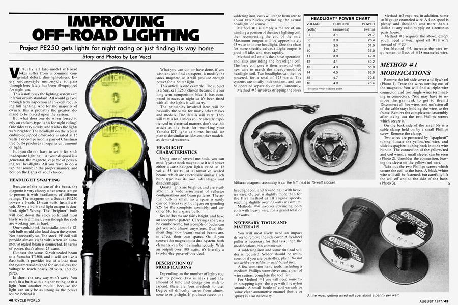
Method # 1 is simply a matter of unwinding a portion of the stock lighting coil, then reconnecting the end of the wire. Maximum output will be approximately 63 watts into one headlight. (See the chart for more specific values.) Light output is good off idle, and rises rapidly.
Method #2 entails the above operation, and also unwinding the brakelight coil. The bare coil core is then rewound with new wire to match the already-modified headlight coil. Two headlights can then be powered, for a total of 125 watts. The systems are totally independent, and can be operated separately or simultaneously.
Method #3 involves stripping the stock headlight coil, and rewinding it with heavier wire. Output is slightly more than for the first method at all engine speeds, reaching slightly over 70 watts maximum.
Methods #4 involves rewinding both coils with heavy wire, for a grand total of 140 watts.
NECESSARY TOOLS AND MATERIALS
You will most likely need an impact driver to remove the side cover. A flywheel puller is necessary for that task, then the modifications can commence.
A soldering iron and some tin/lead solder is required. Solder should be resincore, or if you use paste-flux, plain. Do not use acid-core solder or acid-based flux.
A few common hand tools, including a medium Phillips screwdriver and a pair of wire cutters, complete the tool list.
For Method # 1 you will need some Viin. strapping tape—the type with fine nylon strands. A small bottle of coil varnish or some clear automotive enamel (bottle or spray) is also necessary.
Method #2 requires, in addition, some #20 gauge enameled wire. A 4-oz. spool is plenty, and shouldn’t cost more than a dollar at any radio supply or electronics parts house.
Method #3 requires the above, except you’ll need a 4-oz. spool of #18 wire instead of #20.
For Method #4, increase the wire requirement to 8-oz. of # 18 enameled wire.
METHOD #1 MODIFICATIONS
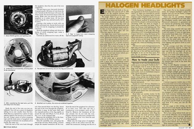
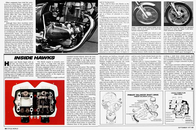
Remove the left side cover and flywheel (Photo 1). Trace the wires coming out of the magneto. You will find a triple-wire connector, and two single wires terminating in connectors. (You may have to remove the gas tank to get to them.) Disconnect all five wires, and unfasten all of the cable stays holding the wires to the frame. Remove the complete coil assembly after taking out the two Phillips screws which secure it.
On the back side of the assembly is a cable clamp held on by a small Phillips screw. Remove the clamp.
Two wires are protected by “spaghetti” tubing. Locate the yellow/red wire, and slide its spaghetti tubing back into the wire bundle. The connection of the yellow/red and coil wires, a small sleeve, can be seen (Photo 2). Unsolder the connection, leaving the sleeve on the yellow/red wire.
Take out the two Phillips screws which secure the coil to the base. A black/white wire will still be fastened, but carefully lift the coil off and to the side of the base. (Photo 3).
Study the end of the wire you just unsoldered. You will see a piece of spaghetti tubing on its end. smaller than the first. Note that it is captured by a piece of tape which is held by the last five or so winds of the coil. Using a piece of nylon strapping tape and the same piece of spaghetti, you are going to terminate the modified coil in exactly the same way.
Push the end of the wire back through the spaghetti, then free the end of the wire completely.
The next step is easy, but easily botched. Unwind exactly 120 turns of wire from the coil. Varnish on the first layer will cause the wire to stick, but successive layers come off easily. Make sure you retain the piece of spaghetti as it comes loose. (If you lose count along the way, unwind exactly 32 ft. of wire.)
Leaving a few inches to work with, cut off the unwound wire. Secure the loose end of the coil wire by wrapping it around the coil form.
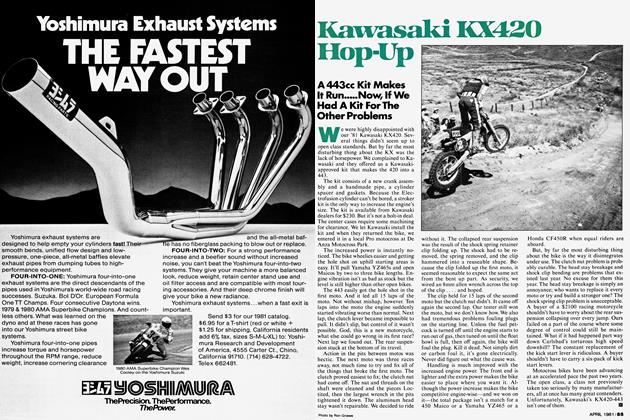
With the spaghetti tubing and about six inches of nylon strapping tape, make a “flag” (Photo 4).
Unwind an additional five turns off the coil, then rewind them over the flag. Insert the end of the wire through the spaghetti, and draw it snug. At the same time, pull the exposed portion of the flag tightly, to secure the wire end (Photo 5). Cut off all but '/s-in. of the exposed tape.
Remount the modified coil to the base, using Loctite on the Phillips screws.
Turn the assembly over, and grasp the end of the coil wire. With a knife, carefully scrape the enamel insulation off the wire from the end of the spaghetti for a distance of at least '/4-in. (You also can use a commercial wire-stripper such as GC Strip-X.) Remove the insulation all the way around, but do not nick the wire. Engine vibration could cause a nicked wire to break. Cut the wire '/4-in. from the end of the spaghetti. Make sure the large piece of spaghetti tubing is still on the yellow/red wire. Resolder the connection, making sure the two wires are butted up against each other, and the sleeve is centered (Photo 6).
Slide the spaghetti tubing back down over the coil wire and replace the cable clamp (Photo 7).
The coil modification is complete except for a paint job. Apply a coat of coil varnish or enamel over the entire surface of the coil. Use an extra dab or two around the flag for additional security, then let the assembly dry thoroughly (Photo 8).
ADDITIONAL WIRING CHANGES #1
Now that the magneto is willing, the rest of the bike must be able. The stock handlebar switches were fine for a 15-watt system, but are a bit of a security risk since their load has been quadrupled. They are best removed.
Astute individuals may wonder about the current-carrying capacity of the stock wiring. If it makes you feel better, run # 12 stranded wire from the lighting coil to the headlight. Couldn’t hurt, though our 140watt PE has stock wire, and doesn’t seem to suffer.
Wiring a single-filament headlight is simple. Start at the back by replacing the taillight (not the brakelight) bulb with a 12-volt item. PE bulbs are the type that look like fuses, and are available at most auto supply stores.
After mounting the new headlight, run a ground wire from the headlight shell (or ground terminal) to the motorcycle chassis. The spark plug coil is a good place, as Suzuki mounts a ground lug there at the factory.
Connect the headlight hot wire to the grey taillight wire. At this point you have a choice. You can use a 10-ampere SinglePole. Single-Throw (SPST) switch for on/ off control. Or you can use a simple onepin connector. (We opted for the latter on the Baja bike for reliability.) Either device is connected between the junction of the headand taillight wires, and the yellow/ red magneto wire.
It should be noted that if the taillight alone is under power from the magneto, it will burn out. So, if you will be carrying a spare headlight bulb, keep a spare hindlight with it. You’ll need it.
If you plan to run a dual-filament sealed-beam or dual quartz lights, and wish to be able to switch them on the run, a couple of extra wires are necessary. So is a Double-Pole, Double-Throw (DPDT), Center Off switch with a 10-ampere rating. The wiring diagram gives you what you need to wire it right. Don’t forget about the chassis ground wire—it’s necessary.
METHOD #2 MODIFICATIONS
Perform the previous steps up to but not including replacement of the magneto assembly cable clamp (just before varnishing the coil).
Locate the orange magneto wire. It leads to the brakelight coil. Slide the large spaghetti tubing up into the cable sheath to expose the wire connector. Unsolder the wires, leaving the sleeve attached to the orange wire. Turn the assembly over and locate the ground lug held on by the Phillips screw. There is a single copper wire soldered to this lug. Unsolder the wire from the lug.
Remove the two Phillips screws, and the brakelight coil from the magneto base. Do not lose the ground lug.
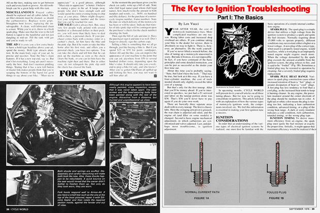
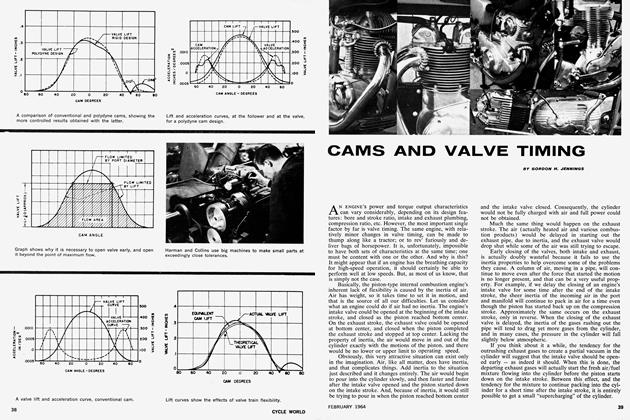
Study the construction of this coil. Except for wire size and the length of the lead wire, it is virtually identical to the previously modified coil. Once its details are memorized, unwind it. Completely. Be very careful that neither of the fiber end insulators (Photo 9) are damaged—they’re fragile. With a dab of contact cement or cyanoacrylate (super-type glue), fasten the insulators to the coil core. As outlined in Method # 1, make a flag using spaghetti and tape. When the glue is dry, rewinding can commence. Carefully grasp the end of the coil core in a vise. Do not over tighten, as the core could be damaged. Slide a couple of inches of #20 wire through the notch in the fiber insulator, and wind the wire toward you (Photo 10—# 18 wire is shown). Wind the wire as evenly as possible. The winds must be tight, but avoid excess tension which can stretch or break the wire. A wooden ice cream stick may be used to pack the windings closer. A metal tool is a no-no as its use could damage the enamel insulation on the wire. Wind 155 turns of wire on the core. Place the flag on the coil and wind an additional five turns. Secure the end of the coil as was done in method # 1 (Photo 5).
Insulation must be removed from each end of the coil wire. As with the first coil, scrape ‘/t-in. of enamel off the wire adjacent to the spaghetti tubing, then cut it that much longer.
Before prepping the other end of the wire, think about the consequences if you break the wire: You get to start over with a bare coil form. Your mind at rest, strip VAin. of wire clean, Va-in. out from the fiber insulator. Cut the wire to a ‘/2-in. length.
Using the two Phillips screws, secure the coil to the base. Don’t forget Loctite and the ground lug.
Solder the short wire to the ground lug. Turn the assembly over. Check that the large spaghetti is in place on the orange wire. Solder the orange wire to the coil wire. Slide the large spaghetti tubing down over the wire connection. Install and tighten the cable clamp.
Coat both lighting coils with coil varnish or enamel.
ADDITIONAL WIRING CHANGES #2
Trace the orange magneto wire to its connector. The wire originally led from the connector to the brakelight swich. This wire should now lead through an SPST switch or single-pin connector to the #2 headlight hot lead.
If a brakelight is desired, change the bulb to a 12-volt model. The orange wire from the brakelight switch should be connected to the hot wire of the #2 headlight.
If you are using only the # 1 headlight, and need the brakelight, hook the orange brake switch wire to the # 1 headlight hot lead.
METHOD #3 MODIFICATIONS
The third method of magneto modification involves rewinding the lighting coil with larger wire. As in Method #1, the stock lighting coil wire (yellow/red) is unsoldered. Also unsolder the black/white and coil wires from the ground lug. Remove the coil from the base, and carefully remove all the stock wire. Glue the fiber end insulators on the coil core, and set it aside to dry.
continued on page 85
continued from page 53
With the small piece of spaghetti tubing and nylon strapping tape, make up a flag.
Grip the coil core in a vise. Using # 18 enameled wire, feed several inches through the notch in the fiber insulator. Wind the wire toward you as in Photo 10. This heavier wire must be pulled tighter than the #20 wire, and the use of a packing tool (ice cream stick) will be necessary. The bottom layers are most critical, so wind them carefully.
Approximately 145 turns are required to obtain the necessary output. Six layers of tightly packed wire will have to be wound on the coil form, occupying virtually all of its available space. Do not try to count the number of turns unless you feel a bit masochistic. Instead, concentrate on tension and straightness. When the winding is about lÁ-in. from completion, wind over the flag and secure the wire end (Photo 11). Trim the excess strapping tape and remount the coil on the base. Use Loctite on the screws, and make sure the ground lug is in place.
Strip the enamel off the wire ends as described previously. Solder the black/ white and coil wires to the round lug (Photo 12).
Turn the assembly over, and solder the coil wire to the yellow/red wire. Slide the large spaghetti tubing over the connection, and replace the cable clamp.
Coat the modified coil with varnish or enamel, and set aside to dry.
ADDITIONAL WIRING CHANGES #3
Perform the same wiring changes as for Method * 1.
METHOD #4 MODIFICATIONS
After winding the lighting coil with # 18 wire, unsolder the brakelight coil wires (orange and ground) and remove the coil from the base. Rewind this coil with # 18 wire as you did the last. Remount the coil on the base, solder the wires, and button it up. You should be great by now! Paint it and you’re done.
ADDITIONAL WIRING CHANGES #4
Perform the same wiring changes as for Method #2.
KEEPING IT LIGHT
Well, you've literally got it wired now. If instructions were conscientiously followed, the system works. Should your first at tempt be less than expected. try it again. Even with the high price of copper. an other buck should be all it takes to see the light.