Making Kawasaki's Superbike Super
MAKING KAWASAKI'S SUPERBIKE SUPER
LOW-COST MODS YOU CAN PERFORM AT HOME
WALT FULTON
LARRY RICHARDSON
EVER WANTED to make a good thing better, but weren’t sure how to go about it? Or perhaps you didn’t think you had the money or the tools. Well, with the aid of this article, an outlay of around $125 for parts, and some very common tools, you can transform your Z1 from something good into something superior.
This begins the three part series we announced last month. The first installment deals with mods and services that you can perform in your home workshop at nominal expense. Those of you who don’t own a Z should keep in mind that the following suspension and traction modifications aren't limited to the 900. Chances are that your bike also suffers from similar problems that can be cured in the same manner.
FORKS
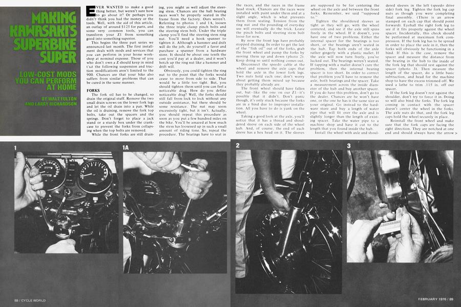
The fork oil has to be changed, so drain the original stuff. Remove the two small drain screws on the lower fork legs and let the oil drain into a pan. While the oil is draining, remove the fork top bolts, take out the spacers and the springs. Don’t forget to place a jack stand or a sturdy box under the crankcase to prevent the forks from collapsing when the top bolts are removed. While the front forks are still draining, you might as well adjust the steering stem. Chances are the ball bearing races won’t be properly seated in the frame from the factory. Ours weren’t. Referring to photos 1 and 1 A, loosen the three triple clamp pinch bolts and the steering stem bolt. Under the triple clamp you’ll find the steering stem ring nut. You’ll need a hook spanner to tighten it. Although a hammer and drift will do the job, do yourself a favor and purchase a spanner from a hardware store. It should be about one tenth the cost you’d pay at a dealer, and it won’t botch up the ring nut like a hammer and drift will.
Obviously, you could tighten the ring nut to the point that the forks would cease to move from side to side. That would be a little too tight. But, you should tighten them until you can feel a noticeable drag. How do you define noticeable drag? Well, the forks should still fall from lock to lock without any outside assistance, but there should be some resistance. The nut may seem excessively tight, but it isn’t. Actually, you should repeat this procedure as soon as you put a few hundred miles on the bike. You'll be amazed at how much the stem has loosened up in such a small amount of riding time. So, repeat the procedure. The bearings have to seat in the races, and the races in the frame head stock. Chances are the races were installed with paint under them and at a slight angle, which is what prevents them from seating. Tension from the ring nut and the pounding of everyday use will eventually do the trick. Leave the pinch bolts and steering stem bolt loose for now.
By now the front legs have probably stopped draining. In order to get the last of the “fish oil” out of the forks, grab the front wheel and pump the forks by moving them up and down (photo 2). Keep doing so until nothing comes out.
Disconnect the speedo cable at the wheel and remove the axle caps that hold the axle in the lower fork legs. Two nuts hold each one; don’t worry about getting them mixed up because they probably already are.
The front wheel should have fallen out, but —like the one on our Zl—it’s possible that it didn’t. Don’t panic though, it’s only stuck because the forks are in a bind due to improper installation. All you have to do is yank on the wheel.
Taking a good look at the axle, you’ll notice that it has a thread and shouldered sleeve on each side of the wheel hub. And, of course, the end of each sleeve has a hex head on it. The sleeves are supposed to be for centering the wheel on the axle and between the front forks. Remember, we said “supposed to.”
Tighten the shouldered sleeves as tight as they will go, with the wheel centered, and see if the axle still spins freely in the wheel. If it doesn’t, you have one of two problems. Either the internal spacer for the bearings is too short, or the bearings aren’t seated in the hub. Tap both ends of the axle rather gingerly with a plastic mallet. If the axle will now turn freely, you’ve lucked out. The bearings weren’t seated. If tapping with a mallet doesn’t cure the problem, then the internal bearing spacer is too short. In order to correct that problem you’ll have to remove the axle, both bearings and the spacer. Take a measurement across the inside diameter of the hub and buy another spacer. If you do have this problem, don’t go to the dealer. Chances are he won’t have one, or the one he has is the same size as your original. Go instead to the hardware store and buy a length of water pipe that will fit over the axle and is slightly longer than the length of existing spacer. Take the water pipe to a machine shop and have it cut to the length that you found inside the hub.
Install the wheel with axle and shouldered sleeves in the left (speedo drive side) fork leg. Tighten the fork leg cap nuts as though you were completing final assembly. (There is an arrow stamped on each cap that should point forward). Eyeball the right fork leg to see if it fits properly against the wheel spacer. Incidentally, this check should be performed at maximum fork compression. If the fork leg has to be spread in order to place the axle in it, then the forks will obviously be functioning in a bind. If this is the case, remove the spacer and measure the distance from the bearing in the hub to the inside of the fork leg that should rest against the spacer (photo 3). Then measure the length of the spacer, do a little basic subtraction, and head for the machine shop to have the excess trimmed off. We used a lathe to trim .115 in. off our spacer.
If the fork leg doesn’t rest against the shoulder, don’t try to force it in. Doing so will also bind the forks. The fork leg coming in contact with the spacer doesn’t center the wheel in the forks. The axle nuts do that, and the fork leg caps hold the wheel securely in place.
Reinstall the front wheel and make sure that the fork caps are facing the right direction. They are notched at one end and should always have the arrow > facing forward. They can be interchanged from side to side, so make certain they go on the fork leg they fit best.
SUPER SUPERBIKE
Now, as shown in photos 6 and 6A, loosen the steering stem fork tube pinch bolts. Use the plastic mallet again to tap these. This allows the fork tubes to center themselves. If not centered, you’ll see the forks move as you tap the bolts. When you retighten the pinch bolts, make sure to do the triple clamp before the stem, in order to insure that they don’t move out of position.
Put the lower leg drain plugs back in and fill the forks with 185cc (the factory calls for 165cc) of 10W30 motor oil (photo 7). The multigrade oil won’t froth and will handle changes in temperature without affecting damping.
Reinstall the springs and spacers in the top tubes, replace and tighten the fork top bolts and hook up the speedo drive. Make sure that you don’t forget to tighten any of the bolts on the fork assembly.
We installed a Goodyear HP on the front because the extra traction will be welcome as soon as we start leaning on the engine. It isn’t absolutely necessary on a stocker, but it is a good tire, and anyone should give it strong consideration when the original rubber wears out. If you do use one, inflate to 26 lb., cold. Throw the rim locks away and make sure that the red dot on the tire is 180 degrees from the filler valve in the tube. Don’t use the rim strip; it will come apart from heat. Instead, use several wraps of duct tape.
REAR END
Modifying the rear end isn’t nearly as involved or time-consuming as doing the front forks, but it has to be done. Remove the jack stand or box so that the rear wheel is in the air. Remove the shocks from each side of the frame. Grab the top of the wheel with one hand, and the bottom with the other. Try to twist it. If the swinging arm moves, tighten the self-locking nut on the pivot bolt, which is found on the left side of the bike above the chain guard. If tightening doesn’t cure the problem, the swinging arm will have to be rebushed.
Remove the rear wheel and check up-and-down movement of the swinging arm. It should move freely but with a slight drag. If there isn’t any drag, tighten the pivot bolt lock nut until resistance is felt.
With the wheel out, remove the brake backing plate from the hub and the brake shoes from the backing plate. Using a hacksaw blade, cut into the lining (about one-quarter the thickness), at an angle toward the direction of wheel travel. These grooves force accumulated brake shoe dust and dirt to be scraped off the linings, giving better stopping ability. Feather the leading edges of both shoes with a file. This last modification will prevent the rear brake from being grabby and having as much tendency to self-energize. If you’re in doubt about which side of the shoe is the leading edge, hold the backing plate with linings facing you. The bottom edge of the left lining, and top edge of the right, are the leading edges. Also, the shoes should be roughed up with number 320 sandpaper before reinstalling.
We also equipped the rear wheel with an Eagle IIP. It should have 28 lb. of air, cold, and again the red dot should be 180 degrees from the filler valve. As with the front wheel, the rim locks aren’t necessary and the rim band should be replaced with tape.
The standard shocks on the Z1 are less than adequate. They are sealed, which prevents any modification to them. They should be deposited in the round file and replaced with a pair of S&Ws designed for use on the Z. Progressive springs with a rate of 90-120 lb./in. are used.
Once you’ve reinstalled the rear wheel, chain adjustment, wheel alignment and brake adjustment are all easy to perform. They should be carried out in the following sequence and manner.
The 6mm bolt holding the plastic chain guard at the rear can be removed and the bolt in front loosened. Swing the guard up out of the way so that you can sight down the chain. Move the chain adjusters back until you have about 1.25 in. free play, checked midway between the sprockets.
For alignment, the factory has provided you with adjusting marks on the swinging arm. Forget they’re even there. Sight down the top of the chain and move the adjusters until the chain runs true and the drive and countershaft sprockets are in line.
Now comes the hard part. In order to center the brake shoes, you’ve got to be a bit of a contortionist, unless you’ve got someone to help. Run the brake rod adjusting nut up against the brake arm. Spin the rear wheel and step down on the brake pedal, keeping the brake applied. Facing to the rear, reach over the left side of the bike and grab the top and bottom of the chain in your right hand and tighten the axle nut with your left. Take up the slack in the adjusters and tighten the lock nuts. Double check chain alignment. Adjust the rear brake to feel and replace the chain guard.
ENGINE
Getting the engine up to specs is the final step. Valve lash should be adjusted first. For some strange reason, neither the factory nor most dealers seem able to get bikes to customers with the correct tappet clearance. The following procedure will enable anyone with a little ability to adjust the tappet clearance without purchasing the special factory tool necessary to keep the valve spring compressed while the shim is removed. This method takes a little more time, but can be accomplished with common metric wrenches, sockets and a feeler gauge. A torque wrench must be used when assembling.
Remove the four spark plugs and cam cover after setting the gas tank aside. Be extremely careful to keep the cover bolts and cover together. These 6mm bolts look identical to the ones that hold the cam towers to the head, but are made from a weaker material. They cannot be tightened to the specified torque of the cam tower bolts without breaking.
Take the point cover off the right side of the engine and use the hex head bolt on the end of the crankshaft to turn the engine over.
Get out a piece of paper and pencil and make up a chart similar to ours so that you can keep track of each tappet clearance after you’ve checked it (photo 8). Do all the intakes or all the exhausts first, whatever turns you on; just remember that the lobe of the cam for the tappet you’re checking has to be facing opposite the shim. The factory manual calls for .002 in. to .004 in. We feel this is too tight and could conceivably burn a valve when the engine is run hard. It’s best to shoot for a clearance between > .004 in. and .0006 in. There is a little more top end noise but the engine does run better.
If you find any valves with improper clearance note it on your chart and continue checking until you complete all of them. Almost assuredly you’ll have to make some changes, so pay close attention to what’s coming next. If there are any intakes that need different shims, remove the cam chain idler gear and cam towers after positioning the crank so the number one and four pistons are at TDC. Remove the cam tower on the left side first. Next, remove the bolts holding the other tower in a crisscross manner, a little at a time. Keeping the chain engaged with the cam gear teeth (photo 9), rotate it until it rests against the exhaust cam. Carefully lay it on the head.
Generally, a magnet is all that is needed to remove the shims. When the shims are too stubborn to come off the tappets with a magnet, use a sharp, pointed scribe to pry them up (photo 9). The size of the shim should be stamped on the opposite side. If not, some dummy put them in upside down and the cam lobe wore the numbers off. This means you’ll have to measure them with a micrometer. The shims come in increments of .002 in., the difference between a 245 and a 250 is .002 in. Once you know this, it’s a simple matter of addition and subtraction to select the proper size shim. It's a good possibility that existing shims can be moved around to obtain the proper clearances. This will save a trip to a dealer and money. (See chart). When the intake side shims are changed, pick the cam straight up, make sure all slack is out of the chain and roll the cam back to its original position.
When replacing the cam towers, you’ll see an arrow on their tops with a number next to it. Make sure the arrow faces toward the front of the engine and the number corresponds with the one on the head. They are also notched for the cam bearing, so make sure the bearing is lined up with the notch before tightening.
Since you removed the cam with some of the valves in the open position, tighten the tower bolts there first (photo 10), bringing the cam down into place without putting any undue stress on it. There is an order for tightening and torqueing the tower bolts (see manual). Maximum torque applied to the bolts should not exceed 13.5 ft.-lb. This point should be reached after working up to it from 9 ft.-lb.
Now remove the exhuast cam in the same manner, starting with the right side, again exercising extreme care that the chain doesn’t jump the sprocket. Follow the same procedure for the intake cam, set tappet clearance, replace the cam and tighten the towers. The cam chain idler gear can be reinstalled in the head. A word of caution: slowly torque the cam tower bolts. They are prone to breakage, but if you can catch them at the point where they snap, they can be unscrewed.
Reinstall the cam cover, but use a little caution when you’re tightening the bolts. They should be snug, but if you turn them too far they will break.
If the cam chain jumps the sprocket for any reason, the cams must be retimed. To do this the engine should still be positioned at TDC on the one and four cylinders. The mark on the exhaust cam should be lined up with the surface of the cylinder head and set in place. Pull the chain tight and fit it onto the cam gear. Starting at the chain link pin just above the sprocket mark, count to the twenty-eighth . pin. There is a mark on the intake cam gear that will coincide with this pin. There is also a mark on the intake cam that will align with the head as it is set into place.
Timing is another area in which proper adjustment must be attained before the maximum can be expected from an engine. Use a flex stone to square the surfaces of each contact breaker. If there is excessive pitting, replace the points. Set the gap at .014 in. Hook a timing light up to the number four spark plug wire (right cylinder). Start the engine and point the light in the hole above the points. Somewhere in there, with the engine at idle, you should see a “1”, a line with the letter “F” below it, and a “4” on the timing advance unit. Loosen the screws on the left point plate and move the plate until the F lines up with the stationary mark above the advance unit. If you can’t get the two marks to line up by adjusting the point plate, the whole backing plate must be moved. When one and four are timed, tighten all the screws, shut down the engine and hook the timing light up to the number three spark plug wire. Start the engine, point the light in the hole and move the right set of points until the “F” under the “2” and “3” on the timing advancer line up with the stationary mark.
Our engine was 7 degrees retarded on one and four and 1 2 degrees advanced on two and three. It is a wise idea to check timing at full advance; two or three degrees one way or the other at the higher rpm becomes critical when striving for maximum output. Full timing advance is reached at 2500 rpm. There are other timing marks to the extreme right of the “4” ahd “3” on the advance unit; they should line up with the stationary mark. If you are interested in maximum power and don’t mind a slightly ragged idle, adjust the timing to full advance.
Last but not least are the four carburetors. Unless you have a vacuum gauge, you must rely on your dealer to dial these in. One thing they sometimes overlook is the air screws. Chances are these are set between a turn and a turn and a quarter out from fully closed. If this is the case, there is probably a flat spot just off of idle that is driving you crazy. Adjust each of these screws to 7/8 turn from closed and that should cure this condition.
Well, was it all worth it? These simple mods make one of the best bikes even better. The tendency of the rear end to pogo when cornering is gone. Now that the forks work without binding and the steering stem is tight, the front end doesn’t wander or oscillate when the Z is ridden hard.
Not only do the tires offer better traction, but the slightly triangular shape of the tread makes the 900 feel as if it were nothing more than a 350.
Next month we’ll show you frame and engine modifications. |§]
RULES FOR WINNING THE Z1
The Z1 described here will be given away at Daytona, courtesy of Kawasaki Motors Corp., Dale-Starr Eng. and CYCLE WORLD magazine. To be eligible to win this production racer, simply put your name, age, address and telephone number on a 3 x 5 post card and mail it to CYCLE WORLD, Box 1757, Newport Beach, CA 92663, by March 1, 1976. You are not required to buy anything, including this issue of CW. You must be 18 years of age or older. Only one entry per person. No employees of CBS or affiliated corporations are eligible. This contest is void where prohibited by law.