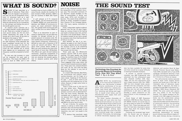
Frames & Suspension
FRAMES & SUSPENSION
TECHNICAL
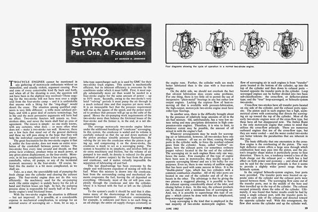
Part one: design and theory
GORDON H. JENNINGS
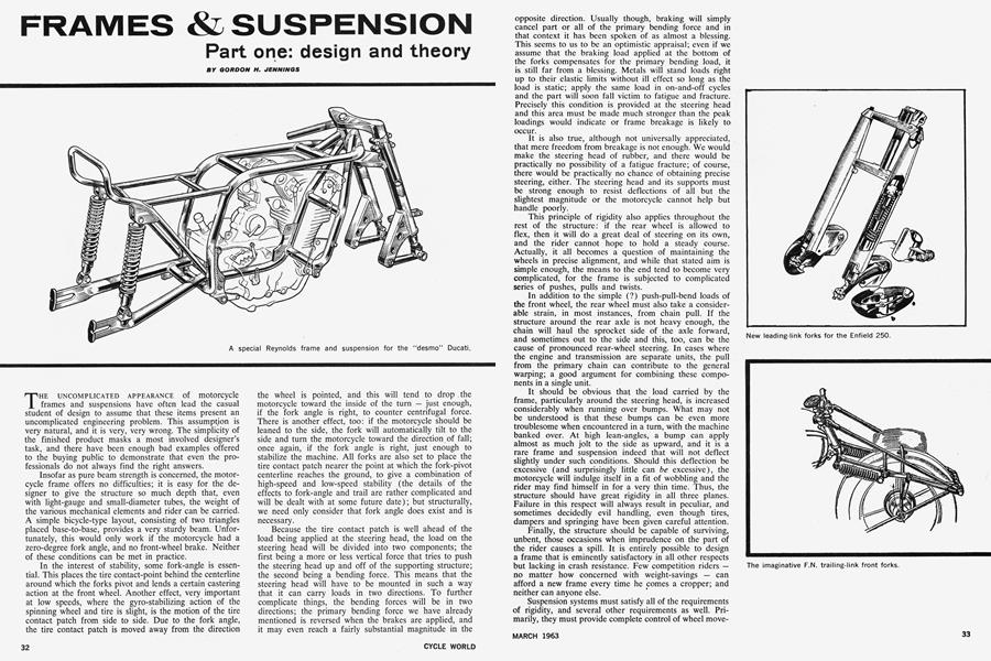
THE UNCOMPLICATED APPEARANCE of motorcycle frames and suspensions have often lead the casual student of design to assume that these items present an uncomplicated engineering problem. This assumption is very natural, and it is very, very wrong. The simplicity of the finished product masks a most involved designer’s task, and there have been enough bad examples offered to the buying public to demonstrate that even the professionals do not always find the right answers.
Insofar as pure beam strength is concerned, the motorcycle frame offers no difficulties; it is easy for the designer to give the structure so much depth that, even with light-gauge and small-diameter tubes, the weight of the various mechanical elements and rider can be carried. A simple bicycle-type layout, consisting of two triangles placed base-to-base, provides a very sturdy beam. Unfortunately, this would only work if the motorcycle had a zero-degree fork angle, and no front-wheel brake. Neither of these conditions can be met in practice.
In the interest of stability, some fork-angle is essential. This places the tire contact-point behind the centerline around which the forks pivot and lends a certain castering action at the front wheel. Another effect, very important at low speeds, where the gyro-stabilizing action of the spinning wheel and tire is slight, is the motion of the tire contact patch from side to side. Due to the fork angle, the tire contact patch is moved away from the direction the wheel is pointed, and this will tend to drop the motorcycle toward the inside of the turn — just enough, if the fork angle is right, to counter centrifugal force. There is another effect, too: if the motorcycle should be leaned to the side, the fork will automatically tilt to the side and turn the motorcycle toward the direction of fall; once again, if the fork angle is right, just enough to stabilize the machine. All forks are also set to place the tire contact patch nearer the point at which the fork-pivot centerline reaches the ground, to give a combination of high-speed and low-speed stability (the details of the effects to fork-angle and trail are rather complicated and will be dealt with at some future date); but structurally, we need only consider that fork angle does exist and is necessary.
Because the tire contact patch is well ahead of the load being applied at the steering head, the load on the steering head will be divided into two components; the first being a more or less vertical force that tries to push the steering head up and off of the supporting structure; the second being a bending force. This means that the steering head will have to be mounted in such a way that it can carry loads in two directions. To further complicate things, the bending forces will be in two directions; the primary bending force we have already mentioned is reversed when the brakes are applied, and it may even reach a fairly substantial magnitude in the opposite direction. Usually though, braking will simply cancel part or all of the primary bending force and in that context it has been spoken of as almost a blessing. This seems to us to be an optimistic appraisal; even if we assume that the braking load applied at the bottom of the forks compensates for the primary bending load, it is still far from a blessing. Metals will stand loads right up to their elastic limits without ill effect so long as the load is static; apply the same load in on-and-off cycles and the part will soon fall victim to fatigue and fracture. Precisely this condition is provided at the steering head and this area must be made much stronger than the peak loadings would indicate or frame breakage is likely to occur.
It is also true, although not universally appreciated, that mere freedom from breakage is not enough. We would make the steering head of rubber, and there would be practically no possibility of a fatigue fracture; of course, there would be practically no chance of obtaining precise steering, either. The steering head and its supports must be strong enough to resist deflections of all but the slightest magnitude or the motorcycle cannot help but handle poorly.
This principle of rigidity also applies throughout the rest of the structure: if the rear wheel is allowed to flex, then it will do a great deal of steering on its own, and the rider cannot hope to hold a steady course. Actually, it all becomes a question of maintaining the wheels in precise alignment, and while that stated aim is simple enough, the means to the end tend to become very complicated, for the frame is subjected to complicated series of pushes, pulls and twists.
In addition to the simple (?) push-pull-bend loads of the front wheel, the rear wheel must also take a considerable strain, in most instances, from chain pull. If the structure around the rear axle is not heavy enough, the chain will haul the sprocket side of the axle forward, and sometimes out to the side and this, too, can be the cause of pronounced rear-wheel steering. In cases where the engine and transmission are separate units, the pull from the primary chain can contribute to the general warping; a good argument for combining these components in a single unit.
It should be obvious that the load carried by the frame, particularly around the steering head, is increased considerably when running over bumps. What may not be understood is that these bumps can be even more troublesome when encountered in a turn, with the machine banked over. At high lean-angles, a bump can apply almost as much jolt to the side as upward, and it is a rare frame and suspension indeed that will not deflect slightly under such conditions. Should this deflection be excessive (and surprisingly little can be excessive), the motorcycle will indulge itself in a fit of wobbling and the rider may find himself in for a very thin time. Thus, the structure should have great rigidity in all three planes. Failure in this respect will always result in peculiar, and sometimes decidedly evil handling, even though tires, dampers and springing have been given careful attention.
Finally, the structure should be capable of surviving, unbent, those occasions when imprudence on the part of the rider causes a spill. It is entirely possible to design a frame that is eminently satisfactory in all other respects but lacking in crash resistance. Few competition riders — no matter how concerned with weight-savings — can afford a new frame every time he comes a cropper; and neither can anyone else.
Suspension systems must satisfy all of the requirements of rigidity, and several other requirements as well. Primarily, they must provide complete control of wheel movements, while allowing enough travel to absorb irregularities in the surfaces over which the motorcycle travels. This is, of course, partly in the interest of rider comfort; but it also has a great effect on control. Without some form of springing, every bump in the road would bounce the tire out of contact with the road surface, and braking, acceleration and cornering would be adversely affected. Adhesion between the tire and the road surface is very poor when the two are not in contact. Given a proper suspension system, the bulk of the motorcycle, and the rider, will glide along relatively smoothly, while the wheels and tires follow the contours of the road. This offers a maximum of comfort for the rider, and the best opportunity for the tire to remain in contact with the road. Obviously, though, it is possible to make the suspension too yielding, in which case the upward motion imparted by the bump will carry the tire and wheel even higher than the bump and once again the tire will be out of contact with the road. And, any system that does not include some form of damping will also be bad; without dampers, the suspension will oscillate at its natural frequency, and the wheel will dance wildly over the road surface, with only momentary contact between bounces.
In addition to providing controlled wheel travel, the suspension must not, in allowing the wheels their movement, create any changes in wheelbase, or in the relationship between steering head angle and trail, or act in such a way that driving and braking torque unduly influence suspension behavior. Perfection, in these areas, is unattainable; but effective compromises are a proven possibility.
Broadly speaking, the selection of a rear suspension layout seems to have been made in advance. Experience, and logic, indicate the use of a swing-arm type suspension. Early in the game, there was a lot of experimenting with sliding pillar suspensions, but while these give a vertical wheel movement, and no change in wheelbase, they are subject to highly concentrated stresses — which makes them heavy — and they create problems with chain tension. If the chain is adjusted with the axle at the middle position on the pillars, then it will pull tight with the axle at the ends of travel. Conversely, if enough slack is provided for the chain with the axle at the extremes of travel, then it will hang slack with the axle at the mid-point. Swingarm suspensions act in an opposite manner, with the chain being tightest with the axle midway through its travel, which is a better situation, as it will be running in that approximate position most of the time. Also, there is less total variation in chain tension.
It is, naturally, possible to eliminate changes in chain tension entirely by pivoting the swing arm at the drive sprocket centerline; but there is seldom enough space to permit this, and if the swing-arm pivot is moved in reasonably close to the sprocket the changes in chain tension will be inconsequential. In the final analysis, however, the swing-arm suspension will be used not because it is kind to the drive chain (it is also used on machines having shaft drive); but because it gives moderate changes in wheelbase, the most rigidity for the least weight, and relative freedom from braking torque reactions. Braking torque does try to rotate the swing-arm with the wheel, but this action (which acts on the swingarm pivot to pull the back of the frame down) is more than compensated by the forward tilting of the motorcycle due to weight transference in braking.
A selection of front suspension is not so easily made. Telescopic forks are in high favor today, but there are also leading and trailing links (both short and long) to be considered, and there is even something to be said for the old-fashioned girder fork.
There is good reason for the popularity of telescopic forks: assuming that the forks are parallel with the steering head (as they almost invariably are), the motions of the suspension will cause no variations in trail, and such variations can be the source of unsteadiness. Changes in wheelbase, which do occur as the wheel moves upward and back, do not appear to have much effect on stability.
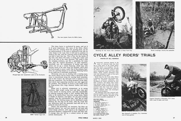
Leading link suspensions have been, and continue to be, quite successful, too. The “Earles” fork used on the BMW is an outstanding example, and it gives a lot of wheel travel and good stability. Braking torque is fed directly into the suspension arms, and this tends to lift the front of the machine when the brakes are applied. However, the lifting force is almost exactly cancelled by the added downward load from weight transfer, and the BMW is, as a consequence, one of the few machines that holds a level attitude even when being pulled to a stop.
Short leading links also give good results. These can be made to strike a nice compromise between constant wheelbase and constant trail, but they cannot be asked to take braking torque, or the front of the machine will actually lift when the brakes are applied. Combine the lifting charactertistics with a bumpy surface, and it is possible to get a wheel-hop that not even the best suspension dampers can control. For that reason, it is customary when using short leading links to provide an extra link between the brake backing-plate and the forks; this arrangement relieves the suspension links of the braking torque and permits them to function undisturbed.
In a few instances, trailing links have been used. That vanished American, the Indian motorcycle, used trailing links and so does the currently-produced Ariel 250 twostroke twin. Trailing links are usually arranged with their pivot well above the axle centerline, so that the path of wheel travel is back as well as upward. This allows the wheel to actually move back a bit when striking a bump, and it therefore glides over the bump a little more easily than would otherwise be the case. This effect is also present, to a lesser extent, in the telescopic fork, but there too it must surely serve to ease the ride somewhat.
The old girder fork is the only one of our four basic suspension types that gives constant wheelbase. The links that control its motions tilt the fork back as it moves up, and down at the axle the movement is essentially vertical. At the extreme ends of the fork’s travel, it departs rather suddenly from its vertical line of motion, and there are sharp practical limits to the amount of travel that can be provided.
In the end, any of the suspension types we have been discussing can be made to yield excellent results. Indeed, there is reason to believe that the best results will come from the layout that possesses the greatest rigidity. An exceptionally inept designer could produce a bad, even though sufficiently rigid, link-type system by building in a grotesque wheel movement path, but this is unlikely. The final choice in this matter will depend (if we ignore cost as a factor) on whether the designer is most concerned with unsprung weight, where link-type suspensions have the advantage, or with steering inertia.
This latter factor is overlooked by many, and yet it is of great importance. The mass of the forks, wheel, brake and tire, rotating about the steering pivot, can be an embarrassment; if the mass is deflected to the side by some bump in the road, then it will tend to continue to swing to the side, until the castering action of the steering can pull it back into line. This is fine, but the inertia of the fork and wheel will make it swing past center and off to the side in the other direction. The result is that the swinging continues, just like a pendulum, for some time after the original disturbance. In some instances, mercifully rare, the combination of inertia and caster action can set up a violent fluttering, which may only become worse if the rider slows the machine, and it may get bad enough to cause a spill. One of the primary functions of a steering damper is to stop this fluttering before it can build up to noticeable proportions.
Obviously, since we are dealing with a rotating mass, the inertia effects will be lowest when a maximum of the mass is concentrated along the steering head centerline, and in that respect, the telescopic fork is superior to any link-type suspension. The far-flung hardware of the links, their pivots and supporting structure can only aggravate the problem. This problem of inertia is also made worse by large-section tires, large diameter brakes and heavy wheels.
When cost is relatively unimportant, as in racing machines, light weight racing tires and alloy rims give a nice answer to steering inertia, and help considerably in reducing unsprung weight as well. Another thing that helps is the double-drum, four-shoe racing brake, which is smaller in diameter, and lighter, for any given braking capacity, than the conventional type. And, also of some importance, the braking torque can be distributed evenly between the two legs of the forks, with the result that any deflections from this particular load will not try to point the wheel off of its line.
Theory and generalities are necessary, but there are practical aspects, too, and next month we will deal with actual design solutions, with regard to the disposition of structural members, configuration of forks and links and, if courage does not fail us, a critical review of some current motorcycles. •