What Makes Them Tick?
What Makes Them Tick?
Inside Suzuki’s Rotary And An Overview Of Its Major Competition
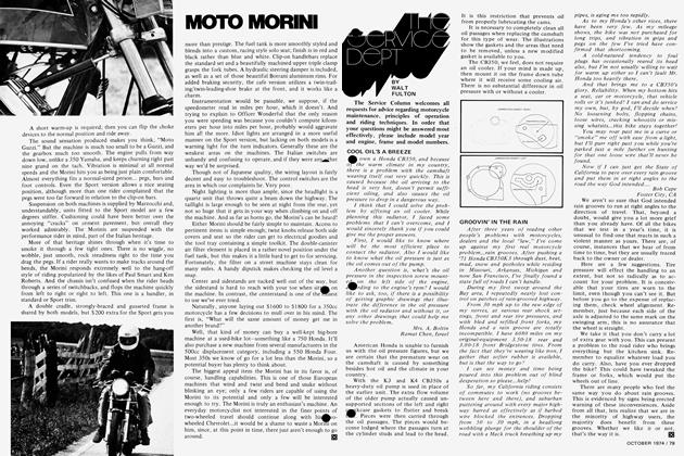
WALT FULTON
As Rod Serling says on television, "Welcome to the world of the rotary." Whether we are welcome to it or not, the rotary is here. And in a big way. Suzuki is the first manufacturer to make this new concept readily available for the two-wheel enthusiast.
The rotary is Suzuki's biggest and most grandiose engineering accomplishment to date. And its hows and whys are so new and usually so misunderstood that it takes a lot of time and a lot of thought to realign one's thinking. In fact, the principles of this engine are so new that dealers—with the exception of regular service work such as timing and oil change—won't be allowed to work on the rotarys. The Suzuki warranty stipulates complete engine replacement if anything goes wrong within 12 months or 12,000 miles. That isn't bad, is it? And to insure lack of trouble, all dealers who intend to purchase a rotary must first send a mechanic to Suzuki's rotary school before they can receive one. That is a step in the right direction for consumer protection. Other manufacturers take heed.
Suzuki crams at least a month's worth of information into a week-long seminar for the dealers. We covered the same information in only a day. Needless to say they had our full, undivided attention. The real lifesaver was Geoffrey Mazon, supervisor of the technical department, who could get the important points across quickly. Geoff, by the way, also handles all the service schools at the present time.
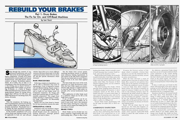
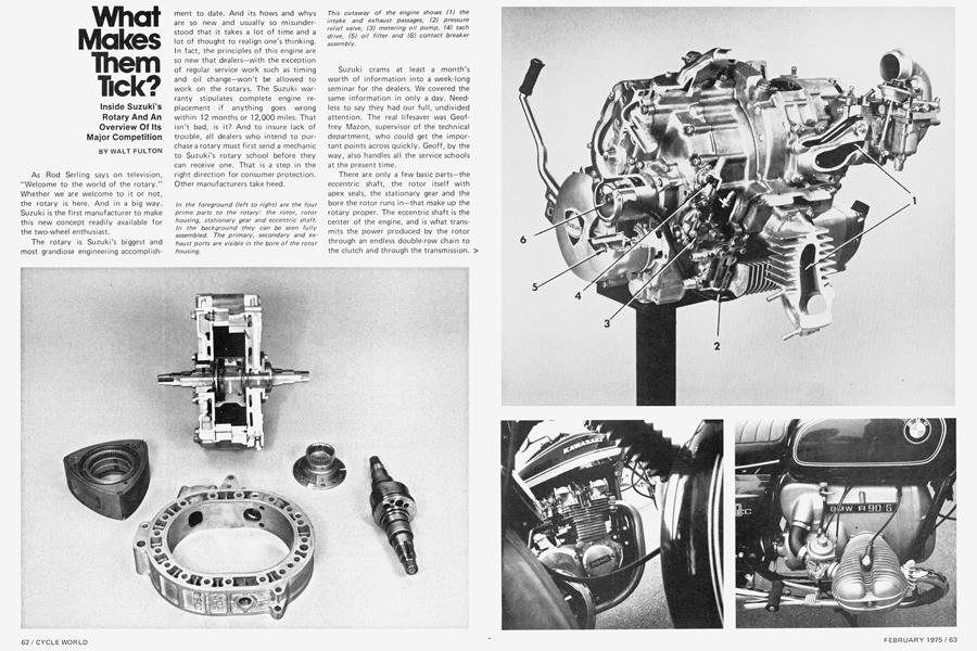
There are only a few basic parts—the eccentric shaft, the rotor itself with apex seals, the stationary gear and the bore the rotor runs in—that make up the rotary proper. The eccentric shaft is the center of the engine, and is what transmits the power produced by the rotor through an endless double-row chain to the clutch and through the transmission. > On the shaft is an offset circular surface that the rotor runs against. This is referred to as the "bulge." The eccentric shaft rotates inside a stationary gear that is fixed to the rotor housing.
Boing Boing Boing Hmmmmmmmmmm
The pressure of combustion exerts a downward force on the rotor. This forces the rotor directly away from the combustion face. This downward motion causes the eccentric shaft to rotate. The rotor revolves, or, if you will, moves in an orbit. Because the teeth of the internal gear and the stationary gear are meshed, the rotor has to rotate. In other words, the revolving rotor is compelled to "roll" around the fixed gear.
It is at first hard to picture the fact that the rotor revolves and rotates at the same time. But, look at it this way. Do you remember a thing called planetary motion? The earth rotates on its axis, while at the same time revolving around the sun. Well, the same thing happens here.
The bore shape of the rotary is referred to as a trochoid. By definition a trochoid is a curve traced by a point on a radius, or an extension of the radius of a circle that rolls, without slipping, on a curve, another circle, or a straight line. A look at the illustrations will clarify this.
Two prefixes that we need to know are "peri" and "epi." The former denotes "around or about," the latter "on or near." Both of these are modified trochoids. It's enough to say that if the "e" for eccentricity and the "r" for generating radius (in the illustration) are the same, the two corresponding shapes are identical. For what it's worth, Suzuki uses the peritrochoid and Mazda the epitrochoid method to design their rotary engine cylinders. The exact shape of the rotor is determined from the dimensions of the trochoid.
The seals on the rotor ends are called apex seals and they correspond to piston rings in ,a piston engine. The sealing surface at each of the three apexes is comprised of a three-piece seal.
Like the two-stroke engine, there are ports in the cylinder to allow the passage of the intake and exhaust products. The timing is determined solely by the position of the rotor. The rotor with its apex seals closes the ports off. These seals are designed to allow pressure under them, thus creating a seal against the cylinder wall.
Before we get too far afield, we should mention that the rotor itself has myriad seals to prevent blow-by or leakage due to high combustion pressures.
Engine lubrication is accomplished by none other than a trochoidal pump. The eccentric shaft runs in large, plain bearings. These dissipate heat better than roller or ball bearings and have no problem handling the loads imposed upon them. Oil pressure runs in the neighborhood of 100 psi. Oil being drawn up by the pump is first routed through an oil filter, from there to an oil cooler and then into the rotor where the internals are cooled as the oil returns to the sump. This takes care of cooling and lubricating the rotor and the eccentric shaft, but the apex seals on the rotor also need lubrication.
The seals are lubed by a metering oil pump whose rate of flow is regulated by > throttle opening and engine speed. This oil comes from an external tank, through the pump and into the carburetor, to be mixed with the fuel from the tank. Mixing, which is done in the carburetor, is at a ratio of approximately 100:1.
The inlet port in the RE5 is actually two separate ports, one the primary and the other the secondary. The carburetor is a two-barrel, two-stage mixer. The primary and secondary bores correspond with the inlet ports. The throttle valve in the primary bore is actuated by the throttle grip. On the other hand, the secondary valve opens and closes in accord with the vacuum present in this bore.
In the inlet port itself, there is a third valve referred to as the port valve. The port valve is also controlled by the throttle grip; however, it is adjusted to open a predetermined number of degrees after the primary port, in this case 41.
The prime function of the port valve is to prevent the fresh charge of fuel and air from mixing with the exhaust gases on "port overlap." At the higher engine speeds this is not an important factor. As the primary valve is opened to its maximum, the port valve also opens. At the same time the engine is picking up revs and the vacuum increases, opening the secondary valve until full throttle is reached.
Up until this point, all of the systems have been trick or out of the ordinary. The ignition is no different. Most systems are either pointless or have one set of points for one or more cylinders. The RE5 has two sets of points for one cylinder. They are positioned one on top of the other and actuated by two separate cams, one having a single lobe and the other two. Under normal operation, only the two-lobe cam functions, that is to say, below 1700 rpm, under acceleration or at cruising speeds.
(Continued on page 101)
Continued from page 66
There is a vacuum switch connected to the carb and a speed relay from the tach that will put the single-lobe cam into play. This speed relay completes part of the circuit above 1700 rpm; the vacuum switch completes the other part when the vacuum is high enough to close the circuit under deceleration. The points are hooked up in series, which means that they both have to be open before the ignition circuit can be completed. This happens every other rotation of the shaft.
The reason for this is as follows: When decelerating, the fuel mixture is thinned because of the exhaust gases mixing with the intake mixture on port overlap. Every other face of the rotor is fired, which produces a smoother running engine on deceleration; this is a condition peculiar to the rotary engine.
It goes without saying that the CDI produces a spark that is more than sufficient to burn the charge of fuel in the cylinder. Also, the points are nothing more than a triggering system, and are not affected by the dwell time. In other words, it is important when they open, but not how long they are closed.
Now that we have fuel, fire, lubrication and the rotary motion, there is one other necessary system that must function: the cooling system. One problem with the rotary that has been overcome is the great temperature difference between the combustion chamber/exhaust port and the inlet tract. This differential could conceivably cause rotor housing warpage. To prevent this, the cooling liquid enters the water jackets at the highest temperature point of the engine, which is the area surrounding the combustion chamber.
The liquid enters the right side housing, passes through the rotor housing, makes a 180-degree turn at the left side housing, and is routed back toward the right side housing by way of the exhaust port. At this point some of the liquid is returned to the radiator. That liquid which didn't make it this time is again directed back through the area around the inlet port. Finally reaching the left side housing, its direction is again reversed and the liquid flows to the radiator where it is cooled and starts its trip again. In effect, the cooling liquid takes heat away from the combustion chamber/exhaust port area and warms up the intake tract.
(Continued on page 106)
Continued from page 101
There are two other new innovations on the rotary that deserve mention. Before the tank must be switched to reserve, a red indicator lamp lights on the dash. This lamp is actuated by a "thermistor"—a thermal resistor—in the tank. As long as the fuel level covers this sending unit, it remains coo! enough to produce a high resistance and little current flow. As the fuel level drops, the thermistor heats up, the resistance lowers and the current begins to flow, which illuminates the warning light.
Also noteworthy is the low oil warning light. This is a switch that utilizes a magnetic float. When the oil level reaches the add-one-quart level, the float causes the switch to close, completing the circuit and again illuminating the warning light in the instrument cluster.
One thing for sure is the complexity of the rotary engine. That, however, also makes it fail-safe. It has systems to back up systems and a theory that will leave most people talking to themselves after the first encounter. Because of this, there isn't much chance of the back yard wrench tinkering with his own toy.
Some people—like those at Suzuki — claim the rotary is the thing of the future. Others—like the Germans—feel that it has good applications in the industrial market, but not between two wheels.
We can look at several of the engine designs used in motorcycles today and see both positive and negative points for all of them. One thing one must realize is the short time that the rotary, as compared to the piston engine, has been in development. At this point the piston engine has many years of development on the rotary, but the rotary appears to be knocking on the door.
Because of the many power pulses of the rotary, its prime selling feature is smoothness; but it may not be long before it is up to par on performance also.
Now that we have examined the complicated and sometimes difficult principles of the rotary, let's have a look at a couple of simpler engine designs.
(Continued on page 110)
Continued from page 106
Even though these two are of different configurations, they both go boing, boing, boing instead of hmmmmmmmmm.
The Kawasaki Z1 was unleashed on the market in late 1972. Until then the Honda 750 reigned supreme, but no longer. The Z1 was a machine that was many years in the planning; the result was a tire-smoking roadster that few could reckon with. In fact, there still aren't many machines that can play in the same league as the Z.
According to present-day standards, the Z1's is pretty much a straightforward design. The cylinders are parallel to one another and inclined slightly forward in the frame. Unlike the Honda Four, the Kawasaki is of a double overhead camshaft design. It is somewhat more complicated than an sohc, but is far more efficient, especially in terms of performance.
Inside the engine is a single-row chain that is driven from a sprocket at the center of the crankshaft. The chain then loops around two separate gears and operates the cams in a hollow cavity between the center two cylinders. The chain is adjusted by a shoe-type adjuster at the rear of the cylinder. The cams themselves run in plain bearings, which is nothing out of the ordinary.
The cam lobes act directly on cups and spacers that cover the valves and springs. Valve-cam lobe clearance is adjusted by varying the thickness of the spacers that set on top of the valves. This is one of the more difficult service procedures necessary on the Z1. It is virtually impossible for an individual to carry out because of the quantity of spacers needed, the price of these and the special tool required to replace them.
The ignition pieces are contained under a cover on the right side of the crankcases. This consists of two sets of points. As on the Honda 750 and other bikes, there is a wasted spark every revolution of the engine. As opposed to the Suzuki, the dwell time is an important consideration with the 903.
With the low-dome, three-ring pistons, the 903 produces an efficient burn pattern. Also, an 8.5:1 compression adds to the longevity of the engine without affecting the performance.
Even with the large engine capacity, cylinder bore is small enough that regular fuel can be used without the
spark getting ahead of itself and causing detonation. Low lead fuel can also be used because of the sintered material used for exhaust valve seats. Tests have proven that premium fuels produce the best results, however.
Fuel and air are mixed together in four 28mm Mikuni carburetors. These aren't as elaborate as the one two-barrel fitted to the RE, but they seem to work just as efficiently. There are covered fittings at each intake port that are used for setting the carbs with vacuum gauges. This is the only way to do it right.
The Z1 was the first bike to come with a smog device. Any blow-by is pumped back into the intake manifold and then to the cylinder for one more try at combustion.
The pressed-together crank rides on large roller bearings. Needle bearings are standard at the big end of the rod. The small end is nothing more than bushings.
Primary drive is from a straight-cut gear on the crank just behind the right outside cylinder. A pinion gear drives the clutch hub. Power is transmitted smoothly from the wet, multi-plate clutch to the transmission.
With a claimed horsepower rating of 82, the Z1 is the most powerful of the three bikes tested. This shows up clearly in quarter-mile and top-speed figures.
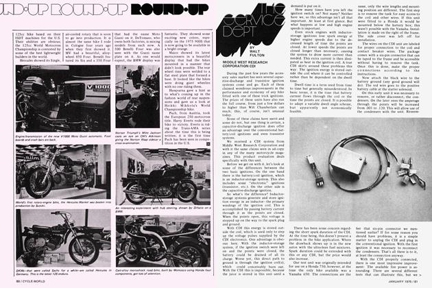
From an engine that goes around, to one that goes up and down with many pistons, to a rather archaic opposed design of only two cylinders, that's what you face when you add BMW to the discussion.
BMW has come a long way from its first shaft-driven motorcycle built in 1923, although it, too, was an opposed Twin. As you can see, BMW and Suzuki are in the same boat, more or less. The opposed-cylinder design is something that BMW has believed in for years and is pushing with ever greater success. Suzuki is gearing up to get behind the rotary concept 100 percent. The difference is that one design is tried and proven, the other an unknown.
When BMW went from the conventional 750 to the larger 900, some internal changes were necessary to maintain engine strength and reliability. Case castings had to be reinforced with more material at the key stress points, particularly around the front and rear main bearings.
The crankcase opening was reduced in size, which necessitated reducing the overall diameter of the crankshaft. Crank balance is now accomplished by attaching heavy metal inserts.
(Continued on page 112)
Continued from page 110
The crankshaft is a single-piece steel drop forging. It is supported by large plain bearings at either end. It is dynamically balanced to reduce vibration to a minimum; however, the large 900 begins to tingle at approximately 4500 rpm. The 750 is much smoother.
The l-section rods are also dropforged and run on four-layer plain bearings. The small end bearing is a pressed-in bronze bushing.
A case-hardened phosphatized diecast camshaft is located directly below the crank. It is driven at half engine speed by a duplex chain. Any chain stretch is compensated for by a chain tensioner operated by a leaf spring.
The cam is located directly in the crankcase at the rear and in an aluminum bearing at the front. Also on the cam is the rotor for the oil pump, the advance mechanism for the breaker assembly and the drive gear for the tachometer.
The cast-iron cylinders are surrounded by aluminum cooling fins. Cooling on the BMWs is most efficient, due to the fact that the cylinders protrude into the air stream.
Pushrods run the length of the cylinder and head to operate two rocker arms per cylinder. These pivot on needle bearings. Valve adjustment is carried out by turning an adjuster screw in each rocker arm in or out from the pushrod.
As with the Kawasaki, the BMW has wet-sump lubrication. Oil is picked up in the sump by a trochoid pump and is forced through the lubrication passages of the engine.
To handle the extra power produced by the 900, the dry single-plate clutch has been beefed up. The famous BMW gearbox clunk has, for all practical purposes, been alleviated by the addition of the five-speed gearbox. All we can say is, it's about time.
A well-protected, water-proofed and ventilated ignition is driven off the camshaft and crank...the points by the cam, and the alternator by the crank.
The biggest advantage to the BMW is the ease with which all service can be carried out. All pieces are out in the open and can be reached with minimal effort. 0
CYCLE WORLD DOES IT BETTER