Baja Lighting Rewire For Yamahas
BAJA LIGHTING REWIRE FOR YAMAHAS
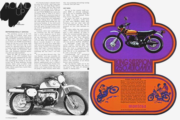
BOLTING ON A PAIR OF QUARTZ IODINE LIGHTS YIELDS A LOT OF POTENTIAL ILLUMINATION. THERE'S NO DOUBT ABOUT THAT. BUT POTENTIAL WITHOUT THE POWER TO OPERATE IT STILL SPELLS DARKNESS!
TECHNICAL:
JERRY GREER
BILL STEWART
LESS THAN adequate headlight illumination is one of the most common problems connected with night-time off-road racing. For the DT-RT series Yamahas, however, there is a solution—a lighting rewire which enables these machines to carry 115 watts of lighting power. Although this amount of headlight wattage is not legal for street use, it can be used for night enduros, general night off-road riding, motorcycle rescue work and high-speed night racing such as the Mint 400 and the Baja races.
The Baja lighting rewire, if you will, is not particularly difficult, but it is one of those conversions that requires careful attention to detail. If the job is done sloppily, you can definitely look forward to loose wires yielding either open circuits or shorts to ground. Either way, ultimate darkness is the result!
Before we get into the actual conversion, let’s take a look at a typical off-road, night set-up and see just where the required 115 watts goes. Ideally, there will be a pair of quartz iodine type lights, such as Cibe units, and these draw 55 watts each. Add 5 watts for the usually required taillight and another 5 watts for a brake light (if you go first cabin) and you end up with a 1 15 watt demand...a demand that cannot be met by most stock bike generating systems!
EQUIPMENT NECESSARY
1. Rosin core solder.
2. Twenty feet of insulated 14-gauge stranded copper wire. 3. One foot of insulated 18-gauge stranded copper wire.
4. One Yamaha YAS2 full-wave rectifier, Part No. 195-81970-1 1-00.
5. One battery, 12V, five to six amp-hour capacity.
6. Two toggle switches, 15 amp capacity, two position. Use only high quality switches.
7. A new No. 1 lighting coil identical to the No. 1 lighting coil in your model magneto.
For example:
Note: If your new No. 1 lighting coil is not identical in size to your present No. 1 lighting coil, reduced output will result. If this problem occurs, purchase two No. 1 lighting coils of the same part number to eliminate any possibility of coil mismatch.
8. One or two high-quality quartz iodine lights with a beam pattern to suit your racing needs. Example: one pencil beam and one flood make a good combination for high-speed straight dirt roads.
Manufacturers: 1. Cibe, 2. Hella, 3. Carillo, 4. Lucas.
WIRING INSTRUCTIONS
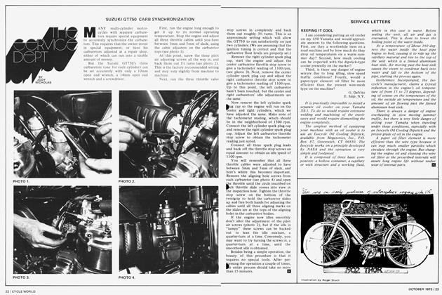
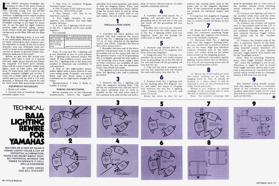
Before making any of the following modifications, remove the magneto assembly from your machine, and orient it with the diagram below. Then, read through the modification steps, identifying the proper wires as you go along. That way, when it comes time to cut and solder, the job will be a lot easier.
1
INSTALLATION STEPS
2
1. Unsolder the black ignition coil ground wire that connects the source coil to the No. 1 lighting coil, and leave IV2 in. of wire attached to the ignition source coil. (Note: Unsolder the wire at the yellow sleeve joint.)
2. Resolder the bare end of the black ignition coil ground wire to the unused grounding tab on the upper left side of the ignition source coil. If no grounding tab is available, ground the wire under a coil mounting screw head, using a steel or brass connector eye available at auto parts stores. Do not use the aluminum types; they break too easily.
The ignition coil is now disconnected from the lighting coils, and is properly grounded.
3
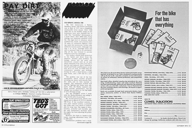
3. Remove the No. 1 lighting coil from the magneto backing plate. Clip off the red insulated wire and the rest of the black insulated wire as close as possible to the coil, and cover each of the exposed wire ends on the coil with a drop of epoxy, silicone seak.nt, or other suitable insulating material.
4
4. Unsolder the solid copper No. 1 lighting coil ground wire from its grounding tab at the left end of the coil, and break off the grounding tab (see diagram).
Unsolder the yellowish-tan stranded copper wire from the solid copper wire at the No. 1 lighting solder post (see diagram). Note: Do not damage the solder post. It will be re-used.
5
5. Remove and discard the No. 2 lighting coil and all of its magneto wire loom wires (see diagram).
6. Using the spare No. 1 lighting coil, unsolder the ground wire (solid copper) from its grounding tab at the left end of the coil and break off the grounding tab (see step No. 4).
7. Clip off the black insulated wire and the red insulated wire and insulate the ends with epoxy (see step No. 3).
6
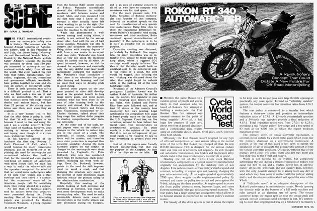
8. Position both No. 1 lighting coils on the backing plate. Per diagram, cut, fit, and solder two pieces of 18-gauge wire between the two No. 1 lighting coils. Connect point (1) to (2), and point (3) to (4).
Route the wires so they do not contact any moving parts, such as the point cam or the magneto flywheel. Note: If the connections in the diagram are crossed, no electrical output will result.
9. Using two 3-ft. lengths of 16-gauge insulated wire, solder one end of each wire to points (2) and (4) shown in step No. 8.
10. Route both 3-ft. lengths of wire under the condenser mounting flange and through the magneto wire harness, out to the multiple connector.
11. Remount both No. 1 lighting coils onto the magneto backing plate. Be very careful not to pinch or stretch any of the wires. High rpm vibration weakens stranded wire at the solder joints, and undue stress on the solder joints speeds up the fatiguing process.
As an additional precaution against lighting system failure due to vibration, Loc-Tite all coil mounting screws and all magneto backing plate screws.
8
12. Mount the YAS2 full-wave rectifier either standing on its bolt, or hanging from its bolt. It should be located in a place where it will be exposed to cool air, but protected from rocks, brush and endos.
Mount it per diagram to prevent breakage of the mounting bolt or rectifier due to vibration fatigue.
Note: The rectifier mounting bolt must be grounded, but no other part of the rectifier should touch anything metal, otherwise a direct short will occur.
13. Connect one lighting coil wire to the rectifier white wire, and the other lighting coil wire to the rectifier green wire. Polarity is not important.
14. Connect the rectifier red output wire to the positive post of the 12V, 6 amp-hour battery, using stranded copper insulated 14-gauge wire and a 15 amp capacity two-way toggle switch. This switch will be the “rectifier switch.”
15. Connect the positive post of the 12V, 6 amp-hour battery to the headlights to be used in your application, using stranded copper insulated 14gauge wire and a 15 amp capacity two-way toggle switch. This switch will be the “headlight switch.”
Note: Due to operating characteristics, both toggle switches' should be “off” when the headlight is not in use. Therefore, it might be best to mount both toggle switches side-by-side to prevent a one-switch-on, one-switch-off situation which would result in a damaged battery if left that way too long.
9
The finished wiring should comply with this diagram. In fact, a continuity check of the complete circuit with a sensitive ohm-meter might not be a bad idea before completely buttoning up the parts on the bike.