The Reed Valve
THE REED VALVE
TECHICAL REPORT:
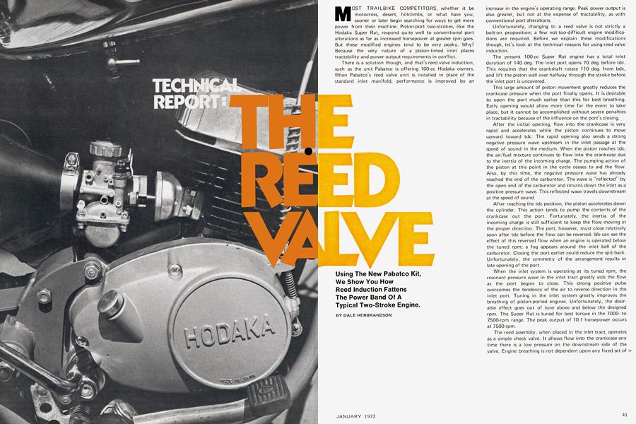
Using The New Pabatco Kit, We Show You How Reed Induction Fattens The Power Band Of A Typical Two-Stroke Engine.
MOST TRAILBIKE COMPETITORS, whether it be motocross, desert, hillclimbs, or what have you, sooner or later begin searching for ways to get more power from their machine. Piston-port two-strokes, like the Hodaka Super Rat, respond quite well to conventional port alterations as far as increased horsepower at greater rpm goes. But these modified engines tend to be very peaky. Why? Because the very nature of a piston-timed inlet places tractability and power output requirements in conflict.
There is a solution though, and that's reed valve induction, such as the unit Pabatco is offering 100-cc Hodaka owners. When Pabatco's reed valve unit is installed in place of the standard inlet manifold, performance is improved by an increase in the engine's operating range. Peak power output is also greater, but not at the expense of tractability, as with conventional port alterations.
Unfortunately, changing to a reed valve is not strictly a bolt-on proposition; a few not-too-difficult engine modifications are required. Before we explain these modifications though, let's look at the technical reasons for using reed valve induction.
The present 100-cc Super Rat engine has a total inlet duration of 140 deg. The inlet port opens 70 deg. before tdc. This requires that the crankshaft rotate 110 deg. from bdc, and lift the piston well over halfway through the stroke before the inlet port is uncovered.
This large amount of piston movement greatly reduces the crankcase pressure when the port finally opens. It is desirable to open the port much earlier than this for best breathing. Early opening would allow more time for the event to take place, but it cannot be accomplished without severe penalties in tractability because of the influence on the port's closing.
After the initial opening, flow into the crankcase is very rapid and accelerates while the piston continues to move upward toward tdc. The rapid opening also sends a strong negative pressure wave upstream in the inlet passage at the speed of sound in the medium. When the piston reaches tdc, the air/fuel mixture continues to flow into the crankcase due to the inertia of the incoming charge. The pumping action of the piston at this point in the cycle ceases to aid the flow. Also, by this time, the negative pressure wave has already reached the end of the carburetor. The wave is "reflected” by the open end of the carburetor and returns down the inlet as a positive pressure wave. This reflected wave travels downstream at the speed of sound.
After reaching the tdc position, the piston accelerates down the cylinder. This action tends to pump the contents of the crankcase out the port. Fortunately, the inertia of the incoming charge is still sufficient to keep the flow moving in the proper direction. The port, however, must close relatively soon after tdc before the flow can be reversed. We can see the effect of this reversed flow when an engine is operated below the tuned rpm; a fog appears around the inlet bell of the carburetor. Closing the port earlier could reduce the spit-back. Unfortunately, the symmetry of the arrangement results in late opening of the port.
When the inlet system is operating at its tuned rpm, the resonant pressure wave in the inlet tract greatly aids the flow as the port begins to close. This strong positive pulse overcomes the tendency of the air to reverse direction in the inlet port. Tuning in the inlet system greatly improves the breathing of piston-ported engines. Unfortunately, the desirable effect goes out of tune above and below the designed rpm. The Super Rat is tuned for best torque in the 7000to 7500-rpm range. The peak output of 10.1 horsepower occurs at 7500 rpm.
The reed assembly, when placed in the inlet tract, operates as a simple check valve. It allows flow into the crankcase any time there is a low pressure on the downstream side of the valve. Engine breathing is not dependent upon any fixed set of timing conditions. This arrangement allows inflow to occur any time there is a demand—and also is not dependent upon a tuning effect in the inlet track for good results.
DALE HERBRANDSON
DYNAMOMETER EVALUATION
To compare the two inlet system designs on a dyno, a series of tests was conducted. First a Super Rat was run in production trim. The cylinder and piston were then modified to accept Pabatco's reed induction. (Alteration of the piston is shown in figure 1.) This allows the reed valve to experience the varying crankcase pressure over the entire engine cycle. The intake opening in the cylinder was then relieved to match the inside of the reed manifold. No spe.cial porting or contouring was done. The engine was then assembled using everything from the previous test. The 24-mm Mikuni carburetor used a 210 main jet in both runs.
Peak torque with this reed engine occurred at 8100 rpm, while the 10.3 horsepower peak was at 8500 rpm. All test data was obtained at the output shaft of the transmission and represents true road horsepower.
Note that the piston-ported inlet resulted in better low end power. This is due to the tuning effect in the inlet system. The reed valve engine peaked at a higher rpm and then hung in there fairly well. Both curves show a power slump at 8500 rpm, due to the characteristics of the stock exhaust system which gives a broad torque curve required in motocross. Since both curves are essentially the same as far as usable power band is concerned, one can conclude that more must be done than just installing the reed valve to get top performance.
The key to the success of the reed valve lies in the additional port area which can be added. The entire cylinder wall above the inlet tract can now be utilized to best advantage.
To prove this, the cylinder was removed and a pair of auxiliary transfer passages were cut in opposite the exhaust port. Each 11-mm-wide port was inclined 30 deg. from the cylinder centerline. These ports are fed from the cavity at the end of the reed valve, which in turn joins the crankcase by the holes cut through the piston. Port height for these "boost ports" is the same as the main transfer passages, and with their addition, almost 50 percent more transfer port area is added to the cylinder. With no further modification the engine was assembled. Results are shown below:
The power increase was quite apparent. Peak torque was at 7700 rpm, while peak power remained at 8100 rpm. In spite of the extra port area and the reed valve, the reed engine was not appreciably better than the stock engine at low rpm. The reed, however, did wonders for midrange power, and resulted in a peak output of 11.8 horsepower. Again, note that both engines have identical carburetion, exhaust systems, and port timing.
For comparison, a high rpm version of the piston-ported engine, a 100-cc Webco unit, was evaluated. This bolt-on kit consists of an aluminum cylinder with a pressed-in steel liner, a matching piston, and a carefully tuned exhaust pipe. The power curve of this unit (courtesy of Webco) is shown below.
Peak torque occurred at 9000 rpm; the peak output of 11.9 bhp was found at the same engine speed. This engine used a 24-mm Mikuni carburetor with a 170 main jet. A 26-mm unit was tried, but resulted in a loss of performance on the 100-cc engine.
The Webco engine has high power, but at the expense of usable 'rpm. This engine, consequently, would require more rider skill than a production Hodaka. It does put out good power, though, and will give the operator a good ride. Again the problem is that of maintaining high power over a wide rpm range.
All of the reed valve testing so far has been with a relatively stock cylinder with no other modifications. Prodded by Webco's successful design, we decided to try our hand at modifying the reed engine. The cast iron barrel was sent to E.C. Burke at Precision Cycle for a port job, which would set up the barrel to match the requirements dictated by the reed valve. Several different exhaust pipes were also made for the dyno test. The port heights in the modified cylinder were left untouched (exhaust opened 92 deg. after tdc; transfer and boost ports opened 115 deg. after tdc). The port contours, however, were carefully modified. A 26-mm Mikuni carburetor with a 220 main jet was also used on the modified reed engine.
Although many runs were conducted with this engine to sort out the various parameters, only two are presented here. The stock Super Rat pipe was used as a starting point. It still produced the lumpy power band. Peak torque occurred at 7500 rpm; the peak power of 12.6 horsepower also occurred at 7500 rpm.
A better power curve was finally obtained with one of E.C.'s so-called "reed pipes." Stinger diameter and length are most critical when tailoring the shape of the power curve. Stinger diameter for a reed valve engine must be much smaller than the 1.0-in. i.d. used on the Rat pipe, and stinger length must also be longer than that on the stock pipe. (Sorry, the finalized dimensions of the exhaust system were not offered for publication.)
The power curve of the modified cylinder, pipe, and 26-mm carburetor were most impressive. Peak torque occurred at 7900 rpm with peak power at 8700 rpm. The 14.5 bhp figure was checked several times during the dyno program. In fact, higher peak power could be obtained through exhaust tuning, but at the expense of a narrower rpm range.
When the stock 24-mm carburetor was installed on this reed engine in place of the 26-mm unit, power in the normal operating range was scarcely changed. The peak torque was unchanged, while the peak power dropped only 1.5 percent. Power above 9000 rpm, however, dropped over 25 percent. One unexpected thing occurred however, and that concerned the temperature rise of the engine during the test. When using the smaller 24-mm carburetor, the cylinder head temperature was difficult to keep in bounds. Larger jetting on the unit caused the engine to run rich and to "four-stroke" at top rpm, so the problem was not in air/fuel ratio. This phenomenon has been known for some time with the fellows who ride in the heat of California's deserts. Very large carburetors are always used. I have seen units as large as 32mm used on a 100-cc reed engine. The 26-mm Mikuni is, therefore, recommended in place of the 24-mm carb for racing purposes with Pabatco's reed induction.
The modified reed engine did not respond to attempts at tuning for power in the 10,000-rpm range. Many reed materials and thicknesses were tried in conjunction with exhaust tuning. The reed's overall flow area is possibly insufficient to pass enough air for high rpm. Once this fact is accepted, the tuner can proceed with the task of sorting out the 8000-rpm range. Peak power and engine flexibility of the reed engine featured in this article are best in this rpm range. These machines should be very strong in motocross events.
ENGINE MODIFICATION
Three changes are required to obtain good power with the Pabatco reed. The first two concern the cylinder. The sketch below shows the reed manifold on a stock Rat cylinder. The sudden step where the reed manifold joins the cylinder must be contoured as shown by the dashed line. A similar step occurs on the sides of this opening, and must be removed. The top of the opening is fine as is; the contour should not even be changed.
The bridge in the center of the port must not be thinned or removed, as it is required for piston guidance. The point where the flow passes through the cylinder bore should be relieved. This removes more of the restriction caused when the piston is in the way of the flow early in the intake process.
The auxiliary transfer passages opposite the exhaust port, as we have seen, are most worthwhile. This is the second engine modification. No dyno work was conducted specifically to evaluate various port shapes, but the configuration used for all dyno runs in this article will, nevertheless, be outlined. The shape and angles were gleaned from the port layouts on various rotary valve engines. The photograph of figure 7 shows the general layout. Ports are 11mm wide and are separated by a web 5mm wide. The projections of the ports converge on the center of the combustion chamber. The angle from the cylinder centerline is 30 deg. Each port was formed by overlapping cuts from a 0.280-in.-diameter end mill.
Note that the overlapping holes give a Gothic shape to the top of the port. This shape was chosen because it created adequate radii on the corners of the opening in the cylinder bore. The goal was to make an opening which would not impair piston ring life. The tips of the single Dykes ring are centered on the web between these auxiliary transfer passages.
The auxiliary transfer passages were not made wider than shown for fear of creating a high pressure zone in the scavenge pattern. This "tongue" would tend to short-circuit through the cylinder and out the exhaust port, a phenomenon which is detrimental to power and fuel economy. Additional work is in order on the size and shape of these ports. Hopefully, they can be made a bit larger without any ill effects.
Finally, the bottom of the piston must be relieved so that it will not interfere with the breathing of the reed valve. The sketch below shows another version of a successful piston modification. Note the difference to the one in Figure 1.
When this piston is placed in the cylinder, the first thing that one notices is that the passage between the crankcase and the boost port can be blocked momentarily. When the piston dwells in the bdc region it blocks the inlet to the crankcase. This inlet cavity is now connected to the inside of the engine by just the boost ports. Any flow through the reed valve at this time would be forced to travel through these auxiliary transfer passages. There is some type of tuning effect taking place in this blocked intake passage, for the engine responds well to this piston design. This configuration was used in the 14.5 bhp engine.
At the time of this writing, the piston evaluation was not far enough along to present the development of an optimized design.
REED STOP
The clamp which holds the reed in place also functions to stabilize the flexible reed when it is off its seat. Bending the stop away from the reeds for greater opening is not advised. The contour is carefully made to optimize performance and maintain reed life. If stiffer reed materials were used, the reed stop would not be required, but such materials sacrifice power above 8500 rpm. It is best to use a flexible reed and control its movement with a contoured stop.
For illustration, the contoured plate on the Pabatco reed was raised 0.024 in. from the reed by using a spacer cut from the base of an old reed. This allowed the standard reed to have more flexibility near its base. The curve below compares the two configurations. The modification helped the power below 7500 rpm, and above 9000 rpm. Unfortunately, the most important part of the power band suffered.
This dip in power was caused by an instability in the reed. Flutter like this also creates a problem with reed life. It is best to run it as it was designed.
REED MATERIAL
Pabatco's reed is a laminated part. Five or six layers of high grade linen cloth are bonded together with phenolic resin under high pressure. The linen/phenolic material combines impact strength with good flexibility and low density. Overall performance of this material has proven to be superior to other laminates of glass/epoxy, glass/melamine, and even steel and beryllium copper.
The linen/phenolic is stamped from preheated sheets. Heat softens the phenolic and reduces the tendency to micro-crack during the punching operation. Life of the reed petal is thus greatly increased.
THE DISADVANTAGES
At an engine speed of 6000 rpm, the reeds will open and close 100 times per second. In just three hours of operation at this speed the reeds will have been cycled over a million times. This cannot go on indefinitely without producing some reed deterioration.
The first indication that the reeds are getting tired will be when they do not lie flat on the reed block. A small amount of tip opening, say 0.5mm, is of no consequence. By the time this figure reaches 2mm at the tip, the power band will change somewhat due to the loss of springiness in the reed petal. Power below 5000 to 6000 rpm will be increased, while output in the 8000-rpm range will go down. Turning the reeds over will temporarily restore the original power. Eventually the tips of the reed petals will begin to fray. If allowed to continue, the reed would eventually not be able to cover the opening. This causes hard starting, but is hardly noticeable once the engine is running.
The resistance to chipping can be greatly improved by hand-sanding the reed tips before installation. All this does is remove any trace of the small cracks formed in the reeds when they are stamped from sheet stock. This broken reed material will not harm the engine, as it is frangible enough to be easily digested with no ill effects. Large pieces of reed never break off—only the reed tips need be inspected periodically. For racers, it is a good policy to change reeds after every major race. The weekend rider, on the other hand, will probably need to inspect them only once a year because his demand on the engine is less severe.
CONCLUSIONS
Reed induction really works on the Hodaka. It offers both high horsepower and a reasonably wide rpm band. The low end torque of a stock Super Rat can be retained while duplicating the top end power of the highly tuned Webco unit.
The superimposed curves above show the results obtained on the dyno. Reed induction seems to be ideally suited for the 100-cc Super Rat. The reed, incidentally, will also fit the two-bolt Ace cylinder.
Required engine modifications for any of the Hodakas are neither complicated nor expensive. It's a good way to make a 100 run like a 125. 0j