Beyond Teledraulics
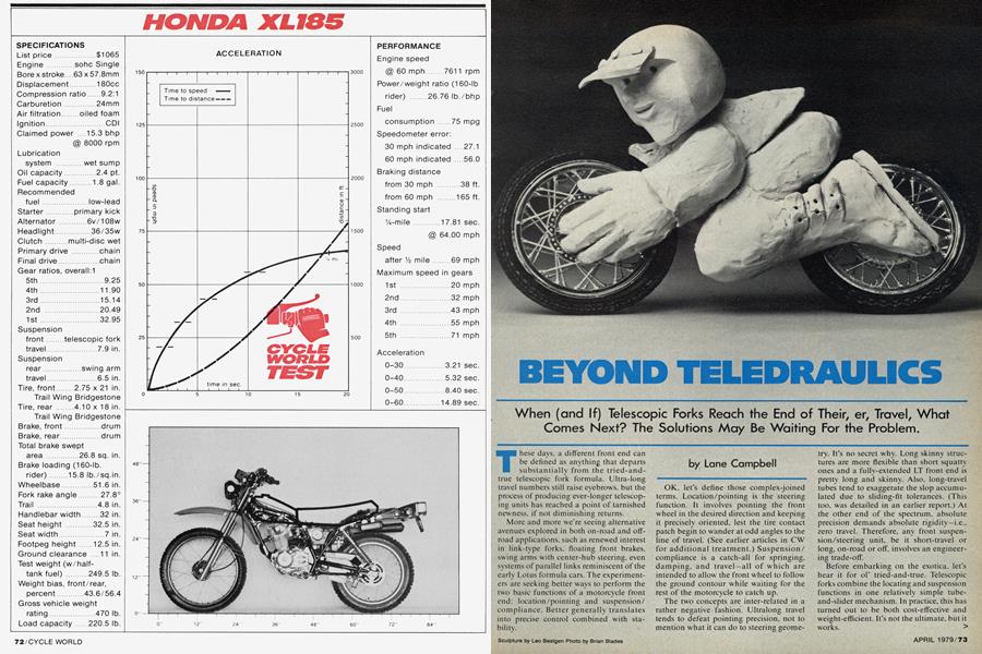
BEYOND TELEDRAULICS
When (and If) Telescopic Forks Reach the End of Their, er, Travel, What Comes Next? The Solutions May Be Waiting For the Problem.
Lane Campbell
These days, a different front end can be defined as anything that departs substantially from the tried-and-true telescopic fork formula. Ultra-long travel numbers still raise eyebrows, but the process of producing ever-longer telescoping units has reached a point of tarnished newness, if not diminishing returns.
More and more we're seeing alternative avenues explored in both on-road and offroad applications, such as renewed interest in link-type forks, floating front brakes. swing arms with center-hub steering, even systems of parallel links reminiscent of the early Lotus formula cars. The experiment ers are seeking better ways to perform the two basic functions of a motorcycle front end: location/pointing and suspension/ compliance. Better generally translates into precise control combined with sta bility. OK, let's define those complex-joined terms. Location/pointing is the steering function, It involves pointing the front wheel in the desired direction and keeping it precisely oriented, lest the tire contact patch begin to wander at odd angles to the line of travel. (See earlier articles in CW for additional treatment.) Suspension! compliance is a catch-all for springing. damping. and travel-all of which are intended to allow the front wheel to follow the ground contour while waiting for the rest of the motorcycle to catch up.
The two concepts are inter-related in a rather negative, fashion. Ultralong travel tends to defeat pointing precision, not to mention what it can do to steering geome try. It's no secret why. Long skinny struc tures are more flexible than short squatty ones and a fully-extended LT front end is pretty long and skinny. Also, long-travel tubes tend to exaggerate the slop accumu lated due to sliding-fit tolerances. (This too, was detailed in an earlier report.) At the other end of the spectrum. absolute precision demands absolute rigidity-i.e., zero travel. Therefore, any front suspen sion/steering unit, be it short-travel or long, on-road or ofE involves an engineer ing trade-off.
Before embarking on the exotica. let's hear it for ol' tried-and-true. Telescopic forks combine the locating and suspension functions in one relatively simple tube and-slider mechanism. In practice, this has turned out to be both cost-effective and weight-efficient. It's not the ultimate, but it works.
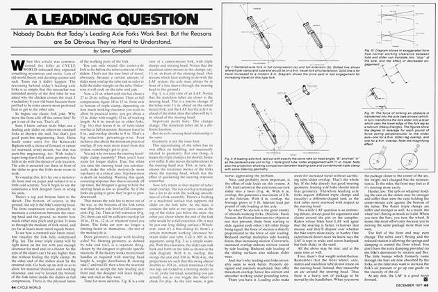
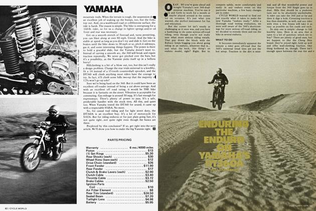
The drawbacks are all too easy to cata log. First, the tubes themselves are flexible. Second. they have an unavoidable amount of slop built in to provide sliding clear ance: wear gradually exaggerates this. Third. they tend to bind under heavy brak ing loads. Fourth. they possess significant unsprung weight: the sliders, plus most of the fork fluid, plus a percentage of the spring weight. plus the damping rods. Fifth, the sliders have a slight tendency to work independently of each other. i.e., one will rise or fall slightly more than the other. thus cocking the wheel from side to side. (Fig. 1).
This last problem is more critical than one might guess. It's called lateral stiffness (or lack thereof)A group of British researchers. Messrs. Roe, Pickering and Zinober. did an SAE paper on the subject (No. 780307) after their studies showed lateral stiffness to be more crucial to steering stability than are wheel loading, steering system inertia, steering geometry (normal variation of rake and trail) or even traction (wet or dry). Table 1 shows their findings, in terms of wobble.
They tested their theories on the computer and in real life. They found that any motorcycle front end will wobble a bit when perturbed slightly. Nudge the steering from straight up. let it go. and the bike will begin to weave, seeking a new steadystate path. Most front ends damp out this wobble sooner or later. This is true so long as the lateral stiffness is high. Even a bike with zero rake and a heavily-loaded front wheel will “damp out” eventually, although it may seem like the granddaddy of all tank-slappers at first.
How ever, w hat if you let lateral stiffness go to pot to the extent that the contact patch can wander from side to side with respect to the steering axis? Then the oscillations magnify, sometimes within only three or four cycles.
Roe. et al. went further in testing their ideas. They designed and built a special leading-link road fork. The thing used very large diameter downtubes. chosen for high stiffness-to-weight performance. Standard shock-spring units nestled inside the tubes, operating on hefty I-beam section leading links. The links pivoted on pre-loaded zero-slop bearings and were tied together by a large-diameter hollow axle.
They tested the unit on heavily-laden touring bikes and found it to virtually eliminate the dreaded top-hamper wobbles. Thev fitted it to a race bike, and here the report retreats into a well-proven Britishism: “The machine was lapping quicker than machines of much higher horsepower." Translation: Thev didn't go fast enough to win. but they sure had fun baiting the lOOOec Flexy Flyers in midpack.
OK. by a roundabout route, we've come to consider link-type front ends. So far. we've established that a link-tvpe front end can be designed and built with extreme rigidity. Further, if the pivot is mounted in rolling-element bearings, the thing should never bind up under braking loads.
Think about this a minute. We said a teledraulic fork was neat because it combines springing and pointing functions in one mechanism. True. However, this one mechanism also has to bear suspension and braking loads from all points of the compass. This is not so neat. The “bearings" in a tele-fork are essentiallv a pair of sliding bushings and are not designed to efficiently cope with omni-directional loading. You gave away something (bearing efficiency) to get something vou wanted (weight, simplicity, cost advantages).
So. a link-tvpe fork uses separate mechanisms for pointing and springing. Braking loads and horizontal road/shock loads get reacted by the link into the pivot. This leaves the spring/damper unit free of side loads that could cause it to bind. (Assuming that the spring/damper is mounted in an interference-free manner, of course.)
Leading-link forks have an additional property, in that they can be set up to counteract braking nosedive. Note I said “can be" set up. Anti-dive doesn't come automatically. The link pivot position has to be deliberately chosen. There's actually an “envelope" of workable geometries, because the ideal geometrv varies with front/rear braking differential.
A second factor is how braking torque is handled. Does it react into the leading link itself from a rigidly-mounted (non-floating) brake anchor? Or will it react directly into the frame via a full-floating brake and a torque rod? It makes a difference.
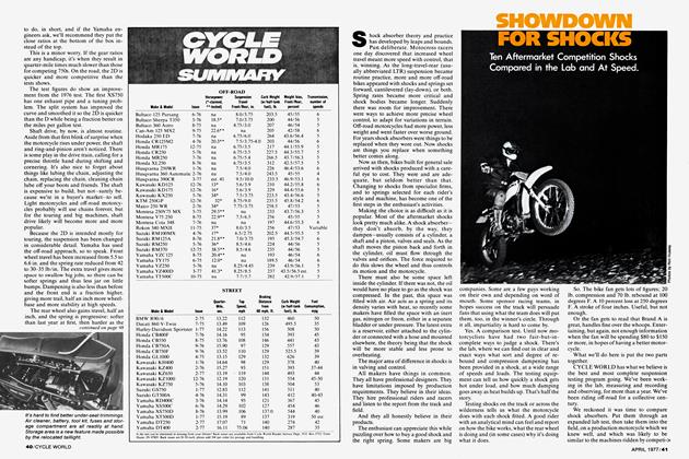
When a single pivot point is chosen, it is “neutral" (neither diving nor lifting) under a special set of circumstances. Case in point: Fig. 2. This free-body diagram of a motorcycle shows c.g.. front-rear contact patches, and a few key dimensions (wheelbase and c.g. location). Suppose the brake is non-floating, and the front wheel does 100 percent of the braking. This front end will be neutral in braking if the link pivot lies on line “I", but will dip if the rear brake is applied.
Suppose the brake is full-floating, and the torque rod is parallel to the fork link. Then the “ideal" link will be parallel to line “1". (Line “f”). Suppose front/rear braking is split 50/50. Then the “ideal" line-of-action will be line “2”. Increasing the proportion of front brake will actually cause this front end to lift. If the braking balance is exactly proportional to front/ rear weight distribution (static), the critical line-of-action will go right through the c.g.
Enough, already. The upshot of all this is that there's a range of possibilities for leading-link geometry. Within this range, the designer makes his trade-offs and takes his choice. It's just as well that there’s a range of workable link locations, for the whole plot is constantly changing. The entire frame settles on its springs under heavy cornering loads, carrying the link pivot w ith it. And the humps and bumps of everyday life w ill gyrate it all over the map. In other words, there had better be a range of usable geometries!
This brings us to a related point; what happens to steering geometry as we hump and bump along over rough ground. More to the point, what happens in the longtravel case? In Figs. 3, a and b. I’ve chosen to illustrate by holding the frame fixed and letting the ground gyrate. All depends on your point of reference. Besides, doesn’t it often seem that way from the rider’s viewpoint (ground/sky/ground . . .)?
Chassis “A” is a typical conventional design with 10-in. fork travel and 8-in. effective rear axle travel. Static rake is 29° and static trail is 5.5-in. If the chassis is rocked to its limits fore and aft. rake varies from a low of 23° (forks fully compressed, rear shocks fully extended) to a high of 35° (everything vice versa). Trail varies between 3 in. and 6.5 in. These days, such changes are considered garden variety radical. Riders allow for them, even use some of them to advantage, compressing the forks to turn quicker on a berm, for example.
Now consider a leading-link fork with the same static parameters. Fully extended. it drops the front wheel so far back from the steering axis that trail becomes a whopping 13 in.! Luckily, the front wheel is lightly loaded at such times, as excessive trail can do some strange things to cornering behavior.
So—if super-long travel is the object, it appears that Round One goes to of Tried ’n’ True. The leading-link fork seems more appropriate to uses that demand high lateral rigidity. This suggests touring, road racing, and of course, any kind of sidehack outfit. In fact, it is in the latter use that leading-links have staged their strongest comeback on-road and off-road. Hacks are a trip all to themselves. We'll acknowledge that they place tremendous sideloads on their front suspension and leave it at that.
Back in the solo world, the need for ultra-long travel tends to defeat the leading-link fork, as we've described it so far. To gain the necessary travel, the link would have to be quite long, so as to minimize the geometry changes shown earlier. That would put the pivot right back against the frame on long, bent fork tubes. Hardly the most rigid or efficient structure. If only you didn't have to steer with it. the bloody fink could actually be mounted to the frame itself. Hmmm . . .
Enter the center-hub steering mechanism. This is an almost diabolical little gadget that places the steering pivot inside the front hub, which, on the surface, makes a lot more sense than hanging it on a framework high over the front wheel. The trick, of course, is getting it in there. The space is, necessarily, limited. (See Fig. 4).
First you have a rigid axle, connected somehow to the frame and suspension. In the center of that axle is an inclined kingpin, upon which the hub pivots to steer. The hub itself carries the spinning front wheel on bearings that are an “outer circle" to the rigid axle. Their ID must be big enough so as not to foul the rigid axle as the unit is steered, lock-to-lock. Their OD must not be so large that linear speed of the outer race becomes prohibitively high. The whole arrangement is a classic shipin-the-bottle puzzle. A definite squeeze.
So what’s it good for? First, it eliminates all that framework normally required to rigidly support a high-set steering head. Early on, this advantage was seized by builders of Bonneville 'liners as a means of reducing frontal area.
Eliminate the steering head and you no longer need a whole lot of frame above or ahead of the engine other than as a place to hang the handlebars. (See Fig. 5). The conventional steering head. way up there high and in front, has always been a source of problems to the designer. It all goes back to frame rigidity, in terms of locating the front and rear wheels in some sort of predictable relationship.
What we're aiming at in this case is to prevent the wheels from being twisted “out of plane" with each other, as was explained in an earlier CW article on frames. In conventional frames, this means creating a rigid connection between swing arm pivot and steering head, as these are the critical “wheel locators" for the chassis as a whole.
With center-hub steering, there's a different system of wheel location. The hub pivots in one plane only, located by the kingpin and controlled by a drag link that's rather car-like in form and function. The kingpin is positively located by the rigid axle, which is in turn rigidly clamped to— say—a swing arm. Now, instead of a swing arm pivot and a steering head separated by over 30 in., you've got a pair of swing arm pivots separated by around 18 in. What we've gained is a simpler, shorter, more direct load path connecting front and rear wheels.
The conventional frame somehow managed to bend the load paths around and over the engine. With center-hub steering, the engine itself can become part of a single, short stubby, and very rigid torque box. As stubby spring-shock units evolve to fit this new configuration, soon the only frame structure above the crankshaft centerline would be that required to support the rider. You get ultra-high rigidity and ultra-low c.g. in one bargain package—a road racer’s dream.
Again, the trick stuff comes with a price, in terms of design trade-off's. First, steering lock is necessarily limited. Center-hub steering is decidedly not the hot set-up for trials.
Second, the complex hub mechanism is, of necessity, heavier than a simple conventional hub. And it's all unsprung weight. This limits its oft’-road potential. So, again, we're looking at applications in which the object is high rigidity and ultra-precision, coupled with reduced frontal area and lowered c.g.
Another quirk to center-hub could be a blessing or a curse, depending on the skill of the designer and/or the adaptability of the rider. Recall that whenever a conventional chassis is “sacked down” in front, this rotates the steering head downward, simultaneously decreasing rake and trail. But look what happens to center-hub geometry in the same situation. The steering pivot is now swing arm mounted, rather than frame mounted: so as the front suspension is compressed, the rake and trail will increase, instead of decrease! (Figs. 6a & 6b).
Now this could lend some strange transient responses to a chassis, unless designer and rider are both aware of the effect. If the front end sacks down under braking, the vehicle will become slower-steering where a conventional chassis would tend to turn quicker. What if the front swing arm has such radical anti-dive that the front end lifts? Now you have the steering becoming quicker, more twitchy, at the same time the whole front end is rising higher off the ground. Could get nasty, couldn't it?
For every problem, there’s a solution, of sorts. Suppose, instead of a swing arm, we use a pair of parallel links to carry the center-hub mechanism. Now the geometry is such that the steering axis is once more tied to the frame. When the frame pitches down, so will the kingpin pitch in the same direction. (Fig. 6c). With this set-up, we’re at least back to normal, in terms of transient response due to steering geometry.
How would you like a kingpin whose effective rake remained constant? Centerhub can be máde to deliver that. too. Instead of parallel links, let’s try a carefully-chosen set of non-parallel, unequallength links to tie the hub to the frame. Choose the right link geometry and the kingpin will hold a constant effective rake/ trail as the frame gyrates within the normal limits of suspension travel. (Fig. 6d).
To those of you who used to hang around cars, the whole lashup should begin to sound like one corner of an earlySixties Formula car. Don't be surprised; the technology was bound to be extended to motorcycles sooner or later. Nor is it a new. untried idea. A California moto-mag, as early as 1970, brainstormed a centerhub design that linked up to a bathtubstyle monocoque frame reminiscent of contemporary race-cars. Last season, the Italians raced a center-hub that used nonparallel link front suspension.
Someday, someone is bound to build a chassis that combines a stressed engine monocoque stub-frame, a double-link (foo-bar) rear suspension with anti-squat, a double-link front suspension with antidive. center-hub steering, air-hydraulic suspension, and fully-floating brakes. I'm not predicting the thing will work. I’m just reaffirming human nature. Someone will do it. just to see if it can be done.
The payoff lies in whatever portion of this exotic technology we eventually see as purchasable “fallout” on production machinery. The contemporary revival of interest in large touring packages may ultimately force a re-examination of standard fork designs for large road bikes. The combination of large displacement, bountiful horsepower, heavy high-set payloads and flexy forks is a problem demanding of a solution.
Strangelv enough, from across the world, among the exotica bred for the European race circuits, there may be a set of solutions already stalking the fringes of practicality, searching for a problem. Maybe by and by they’ll get together.