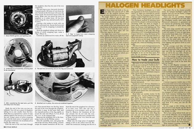
Bright Lights For Your Bike
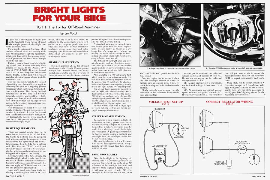
BRIGHT LIGHTS FOR YOUR BIKE
Part 1 : The Fix for Off-Road Machines
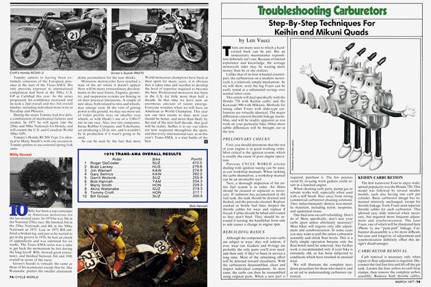
Len Vucci
If you ride a motorcycle at night, you need a headlight. If you ride an off-road bike at night. you need a headlight that works extremely well.
It's a simple statement, but true. Most modern off-road bikes are severely deficient when it comes to lighting equipment. What good does a 30+ horsepower motor serve if you can’t ride faster than 20 mph when the sun sets?
It’s fairly easy to boost your bike’s lighting system, and involves relatively little expense or hassle. In the August, 1977 issue of CYCLE WORLD, we performed such a fix on our long-term Baja-raced Suzuki PE250. In that case, we increased available electrical power almost tenfold, at minimal cost.
This will be a similar article, but instead of providing procedures which are applicable to only one bike, we’ll be giving general procedures which can be used for most offroad applications. The theory behind modifications of this kind can become extremely complex, and would serve little purpose here. Instead, we’ll outline several rules of thumb w hich can be applied w ith success by the relatively inexperienced motorcycle enthusiast.
The procedures outlined here are not simply products of bench-race sessions or untried hypotheses. Except for several bulb failures (most because of foreign object damage), the systems we’ve modified have been 100 percent reliable, not to mention blindingly bright.
BASIC REQUIREMENTS
There are several simple steps to be taken before the fix can be tackled. First, the bike to be modified must be equipped with a lighting coil in the magneto. If your off-road bike has lights which are not battery powered, then the bike has a lighting coil. The Yamaha TT500, which was chosen by reader interest to be our example, has a lighting coil even though it’s not equipped with lights at the factory.
Second, you’ll need to have in hand the actual headlight which is to be installed on the bike, in order to determine what modifications will be necessary. (Obviously, this does not apply to TT500 owners, who can use this procedure specifically.)
Last, you’ll need some basic tools, including a soldering iron and an AC voltmeter, and the skill to use them. In addition to the components which we’ll outline as we progress, you'll also need odds and ends such as heat shrinkable insulating tubing, some glue, and nylon strapping tape. These are nickle-and-dime items which are available at any electronics parts stores.
HEADLIGHT SELECTION
The most common choice for off-road headlamps is the 12-volt 55-watt quartzhalogen unit. Several brands and many models are available and ofi'er a variety of beam patterns and lengths. A combination pattern with good side dispersion is generally best for all-around riding.
A standard automotive sealed-beam unit works quite well for most applications. It’s not nearly as bright as a QH lamp, but it's inexpensive (about two bucks). Its main disadvantage is bulk; instead of a small spare bulb, you have to carry reflector, lens, and all.
The SB and 55-watt QH units are electrically similar and are thus interchangeable. It is a good idea, if you plan to run the quartz unit, to set up your system using a sealed beam. An accidental bulb blow-out is then much less costly.
Also available is a 100-w'att quartz bulb which uses the same reflectors as the 55watt unit. It is definitely brighter, at twice the price of the 55-watt bulb. In addition, its increased power consumption generally means less light at very low engine speeds.
For all-out desert racers it’s possible to run two QH units simultaneously. On a dual-lighting-coil bike, such as the Suzuki PE250, it’s easy and extremely efficient. On a single-lighting-coil bike like the Yamaha TT500, superior dual-lamp illumination is available only at higher engine rpm.
In other words, stick with a single light for each lighting coil unless you're engaged in competition events.
STREET BIKE APPLICATION
Regulations which require taillight illumination by battery power make streetbike electrics very complex. In addition to the need for a battery, provisions must be made for a charging circuit, brakelight, and turn signals. A quasi-legal system may be had by simply wiring a taillight and brakelight into the headlight circuit, but it's not recommended.
The next light hop-up article will cover a 6to 12-volt headlight conversion, using a Yamaha XT500. Street bike fans should hold off till then.
BASIC PROCEDURES
Wire the headlight to the lighting coil, making sure it is properly grounded. As show n in Fig. 1, hook one probe of an AC voltmeter to the headlight hot lead, and the other probe to ground. Set the meter so it will read at least 15 volts AC. (For example, if the scales are 0-5 VAC, 0-50 VAC, and 0-250 VAC, you’d use the 0-50 VAC scale.)
Start the engine but do not rev it above idle. The headlight should be dimly lit, perhaps only an orange glow. If not, recheck the wiring and bulb, and correct the problem.
Slowly bring the rpm up, observing the indication on the voltmeter. Three conditions are possible:
(A) As rpm is increased, the indicated voltage reaches and exceeds 14-volts AC. Do not rev the engine so the indicated voltage exceeds 15 VAC.
(B) As rpm increases up to maximum, the indicated voltage is less than 13-14 VAC.
(C) At maximum operational engine speed, indicated voltage is 13-14 volts AC. If you observe condition C, you’ve lucked out: All you have to do is mount the headlight solidly, hook up the lead wires (#14 or larger) permanently, and you’re done.
More likely will be either condition A (excessive voltage) or B (insufficient voltage). Using the Yamaha TT500 as an example, here are the steps necessary to modify your bike’s lighting circuit for the headlamp of your choice. >
VOLTAGE TEST SET-UP FIG. 1
CORRECT REGULATOR WIRING FIG. 2
CONDITION A: EXCESSIVE VOLTAGE
When we hooked a 12-volt, 55-watt quartz-halogen light into the stock TT500 circuit and ran the engine, a surplus of voltage (and current) was available. The 13-14 volts necessary for proper QH operation was obtained in the engine’s lower mid-range. When the revs approached redline, voltage soared to about 19 volts and the bulb blew, as expected.
FIX #1
The power is available—all one has to do is limit it to a level which can be tolerated by the headlamp. This limiting action can be accomplished most easily b\ wiring a voltage regulator into the circuit. These regulators are available from most of the Japanese manufacturers. A similar device—the Zener diode—is used in many European bikes.
We have had excellent results using an American-made regulator from Henter
Engineering. (This unit should be available from your local accessory or snowmobile dealer. If not. have him contact Henter Engineering, 4561 62nd Ave. North, Pinellas Park. Florida 33565.) The Henter regulator limits voltage to about 13.8 volts, allowing high headlight brightness without blowing bulbs.
It is wired in parallel w ith the headlight, as shown in Fig. 2. Note that if a headlight on/off switch is desired, the regulator should be on the headlight side. If w ired on the magneto side of the switch, the regulator would be working whether the light was on or off.
continued on page 76
continued from page 72
Different regulators require different mounting methods. The Henter unit should be mounted to a flat, solid frame member, but not on the engine itself. The mount provides both an electrical connection and a means of dissipating the heat
produced by its regulating action. On our TT500, we drilled and tapped two blind, shallow holes in the upper triple clamp and used 6mm Hex bolts to mount the unit (Photo 1). Connecting the single lead wire to the headlight hot lead completed the installation.
FIX #2
If you choose not to install a regulator to limit headlight voltage, a lighting coil modification is in order. The general remedy is simple: Remove the lighting coil, and add more turns of wire to the existing coil.
It may seem as though this procedure is backward. If you want less voltage, you reduce the number of turns on the coil, right? Wrong. Seems logical, but it just ain’t so.
Getting down to details, let’s illustrate the procedure, using the TT500. After removing the side cover, yank the flywheel and disconnect the external magneto wiring. Remove the coil assembly and study it to ascertain how the lighting coil is wound and wired. Draw some sketches if they'll help. Once you've got the details down, you can operate.
Slide back the spaghetti tubing to reveal the coil-to-lead-wire joint, then unsolder it (Photo 4). Lift the coil from its base after removing the Phillips hold-down screws.
A piece of thin spaghetti tubing covers the coil lead wire, and is used for stress relief. Slit the tape which secures the tubing and remove it intact.
Using a 4-in. piece of nylon strapping tape (the kind with nylon fibers running through it), make a “flag”, with the spaghetti tubing acting as the “pole” (Photo 5). Set this piece aside for now.
You'll need some additional enameled copper wire to splice onto the coil’s existing wire. Simply take the coil to your local electronics store and have its wire sized and matched. A Va-lb. spool is more than enough, and should set you back less than a buck. (The TT500 wire size is # 19—none was available, so we used #20.)
Scrape the insulation off the end of the wire you just bought. It should be bright and shiny for the last Va-in., and free from nicks which could cause it to break from engine vibration. Prepare the end of the coil wire in the same manner, then bend a small hook in each. Slide a Vi-in. length of heat shrink tubing over the new wire. The prepared wires should compare with those shown in Photo 6.
Hook the two wires together, compress the hooks with a pair of pliers and solder the joint (Photo 7). Slide the shrink tubing over the newly-formed joint, and shrink it with a match. (Photo 8).
Carefully grip the end of the coil in a vise and wind the new wire over the existing wire, in the same direction. Wind 50 turns over the original wires as evenly as possible, keeping firm tension on the wire. When winding over the fresh splice things will get a bit crooked, but do the best you can. At the 50th turn, place the flag on the backside of the coil so the spaghetti tubing points in the same direction as it did when stock. Wind seven more turns over the flag's tape, then cut the wire leaving about 6 in. of free length. Insert the wire through the spaghetti tubing, and draw it tight. At the same time, pull the exposed end of the flag to secure the wire end. After trimming the excess wire, the modified coil should look like the one shown in Photo 9.
Solder the coil wire and lead wire together (Photo 10). then mount the modified coil back on the backing plate.
Slide the insulating tubing back over the solderjoint to complete the electrical modifications.
If you are rewiring a bike other than the Yamaha TT500, you should now reinstall the coil assembly, reconnect the wiring, and replace the flywheel. Perform the voltage test as you first did in the BASIC PROCEDURES section. If the voltage is now too low. you have wound to many turns on the coil. If the voltage is still too high, you must add more turns. Make the proper corrections, in increments of 5-10 turns, until the indicated voltage is 13-14 VAC.
Once the proper voltage reading is attained, the new coil windings should be coated with coil dope or automotive enamel. This will prevent vibration-induced coil failure, and is mandatory for reliability. In addition, the loose wire lead should be glued to the base and coil to keep it from wandering (Photo 11).
Reassembly of the components completes the procedure for reduction of excessively high stock lighting voltage.
CONDITION B: DEFICIENT VOLTAGE
When a 12-volt. 100-watt QH light was hooked to the stock TT500 lighting coil, a maximum of 10 volts was produced. Because the increased load over a 55-watt bulb produced a voltage deficiency, rather than excess, one would assume the fix to be just opposite. Such an assumption would be correct as, within limits, the indicated voltage will increase as the number of coil turns is decreased. Again, we’ll use the TT500 to illustrate the procedure for increasing the lighting coil’s output.
FIX #3
After removing the coil assembly from the bike, unsolder the lighting coil lead and remove the coil. Remove the spaghetti tubing and make a flag using it and a piece of nylon strapping tape, as described previously.
For bikes other than the TT500. unwind 10 turns from the coil, cut the wire, and prepare the end for soldering. Reinstall the coil on the backing plate and resolder the coil wire to the lead wire. (Do not use the flag at this time.)
Start the engine and measure voltage. If necessary, repeat this procedure, unwinding 10 turns at a time, until the voltage reaches 13-14 VAC.
For the TT500. we removed 60 turns from the coil, equivalent in this case to 13 ft. of wire.
When you’ve obtained the proper voltage reading, remove the coil assembly and coil, and unwind an additional five turns. Rewind these five over the flag, insert the wire end through the spaghetti tubing, draw the works tight, and trim the excess wire and flag (Photo 12).
Secure the coil to the backing plate, solder the coil and lead wires together and slide the spaghetti insulator over the bare joint.
Tack down the loose lead with cement, and coat the previously unwound portion of the coil w ith coil dope or enamel ( Photo 13). The modified coil assembly should then be mounted on the engine and the remainder of the components reinstalled to complete the modification.
FIX #4
If you wish to power two headlamps by a single lighting coil, there are several additional considerations.
The original lead wire running to the lighting coil should be replaced by a length of # 14 or # 12.
The aforementioned “unwind 10 turns and re-check voltage” method will work, but beware: Some magnetos just can’t provide the oomph for two lights. You’ll reach a point where unwinding additional coil turns will decrease headlight voltage.
The TT500 can power a pair of 55watters if all but the last two layers of w ire are removed, leaving approximately 110 turns on the core. The two headlights are then spliced into the same w ire as show n in Fig. 2. Installation of a regulator is advised for this dual-light setup. Otherw ise, if one headlamp were to burn out or be broken, the voltage would surge and blow out the remaining light.
SUMMARY
Modification of existing lighting coils for increased output is easier done thnn said. The basic rules are:
(A) Increase the number of lighting-coil turns to decrease voltage.
( B) Decrease the number of lighting-coil turns to increase voltage.
This little bit of knowledge can provide the basis to set up your off-road bike for the lights w hich should have been standard equipment.