Troubleshooting Carburetors: Vacuum, Fixed Venturi, And Lectron Slide.
Troubleshooting Carburetors: Vacuum, Fixed Venturi, And Lectron Slide.
Step-By-Step Techniques For Mikuni CV, Keihin FV, And Lectron.
Len Vucci
The end is in sight. Our series on carburetion is drawing to a close. For interested readers, large expenditures for routine tune-up services should be a thing of the past.
So far in this series of articles, carburetor theory has been presented, as has rebuilding and tuning basics for slide-type carburetors. This final installment will deal with three carburetors other than slide-type.
The constant velocity (CV) carburetor is gaining popularity as manufacturers attempt to combine economy, tractability and performance with low emissions.
The fixed-venturi carburetor is standard equipment on most Harley-Davidson VTwins. Although now manufactured in Japan, its basic design reaches back quite a long way.
The final type of carburetor to be illustrated is the Lectron. Originally conceived to be an aftermarket product, it is to be installed as original equipment on new KTM Pentons.
For each of these types of carburetors, we will offer basic rebuilding and tuning methods.
In our previous carburetion articles, most of the carburetors discussed had been in production for a considerable length of time. Consequently, rebuilding procedures could often be directly applied. The carbs to be discussed here are relatively new, and will most likely be in reasonably good condition.
Many carburetors of an earlier vintage are essentially the same as those illustrated here (Lectrons excluded). For these applications, rebuilding procedures may indeed be necessary.
PRELIMINARY CHECKS
While problems in carburetion do arise, even more frequent are problems in the ignition system. If you are undertaking carb work to cure a sick engine, you had better eliminate the other possibilities first.
If this is to be an attempt at periodic maintenance, there are some associated items which must be dealt with. Air filters, throttle cables, and fuel lines should be inspected. Clean and replace them as necessary. Because the accumulation of sediment is inevitable, the fuel tank should be flushed periodically, and the petcocks cleaned.
REBUILDING BASICS
Fortunately, the solvent action of gasoline in the carburetor keeps it relatively clean. Only when the accumulation of foreign matter becomes excessive is a teardown necessary. Rebuilding a carburetor will most often be a simple disassembly, cleaning, and reassembly process.
Seldom will a carb’s few moving parts wear out. The need for replacement gaskets. seals, or O-rings is far more common. But any part, if excessively worn, should never be put back into the carburetor. The possible destructive consequences far exceed the minimal expenditures required to do it right.
On the subject of destruction, the use of commercial carburetor cleaner is potentially damaging, and therefore ill-advised. While often necessary for a grimy automobile carb, such cleaners can swiftly and permanently damage the non-metallic materials present in most bike carburetors.
Use regular pump gas, a stiff brush, and compressed air if available. Care and patience are the final requirements.
CONSTANT VELOCITY CARBURETION
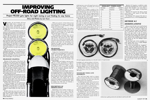
To illustrate a constant velocity (CV) carburetion system, we selected the Yamaha XS750 (Photo 1). This is a triplecarb application, utilizing Mikuni carburetors. The individual carbs are much like the Bing CV units used on BMWs.
Keihin CV carburetors, used on some Hondas and Kawasakis are essentially identical in operation. Construction of the vacuum chamber and slide assembly does differ slightly, however.
CARBURETOR REMOVAL
The fuel tank must be removed after disconnecting the fuel lines and petcock vacuum hoses. Leave the petcocks in the on position—no fuel will flow because the petcocks are vacuum operated. The side covers and air cleaner silencers, held on by Phillips screws (Photo 2), should be removed. Loosen all six carburetor connecting hoses. Remove the four airbox bolts and slide the box to the rear.
Slide the carburetor assembly rearward, so the throttle cable can be removed. The carb assembly (Photo 3) can then be lifted off the bike.
CARBURETOR DISASSEMBLY
Because most of the necessary work can be done without separating the carburetors, that procedure shall not be covered. For clarity in photography, however, the disassembly of a single carburetor will be illustrated.
SLIDE INSPECTION
After removing the appropriate Phillips screws, the carb brackets and tops are removed (Photo 4). The slide springs can be lifted off, and each slide removed. Mark the slides so each can be replaced in its original bore.
Invert the slide to remove the jet needle and retainer (Photo 5). Carefully check the slide diaphragm. A crack or perforation would have a severe effect on carb operation.
FLOAT INSPECTION
Inspect the needle. It should be smooth and straight. Be sure the horseshoe clip is in the same groove in each needle. (Note: Keihin CV carbs do not utilize a diaphragm. Instead, the slide effectively becomes a piston, being drawn up into the carburetor top.)
The float bowl, held on by four Phillips screws, should be removed. By removing the pivot pin, the floats (Photo 6) can be lifted off. Test them for leaks by shaking. The presence of even a small quantity of liquid in either float indicates a leak, and the need for replacement. Inspect the tip of the float needle for wear. If grooved, the needle should be replaced.
JET LOCATION
Jet configuration in the Mikuni CV is rather unusual. The needle jet (Photo 7) is pressed into the carb body, and is heldin place by the float bowl. Check its 0-ring for cracks or brittleness. The pilot jet (Photo 8) is located in the top of the bowl. The main jet (Photo 9) is of the reverse flow variety, and normally covered by the float bowl drain plug.
CARBURETOR BODY
In an attempt to reduce owner tinkering and consequently possible increases in exhaust emission, the idle mixture screw (Photo 10) has a plastic limiting cap. The factory manual flatly states that the original setting must not be changed. Should it ever be necessary to remove this screw, it should be returned to its original position.
If the carburetors are separated, the starting enrichment circuit can be inspected. All internal passages should be blown through, making sure that they are unobstructed.
CARBURETOR REASSEMBLY
Install the float assembly, and place the carburetor on a flat surface, engine side up. With the float resting against the needle, measure the float level (Photo ll). It should be 26 mm. Bend the tab on the float bracket to adjust.
With all three jets in place, replace the gasket and float bowl. Install and tighten the bowl screws and drain plug.
Insert the slide into its bore. Turn it so the two tabs on the diaphragm are engaged in the recesses in the carb body. The needle, nylon retainer, and spring should then be installed in the slide. Finally, the top cover should be replaced, and the bracket and screws reinstalled.
CARBURETOR REINSTALLATION
Connect the throttle cable to the carb assembly, and check for full throttle operation. Adjust the cable if necessary. Install the carbs on the engine, and the airbox on the carbs. Insert and tighten the four airbox bolts, tighten all six hose clamps, and replace the airbox silencers.
Install the side covers and gas tank. Connect the fuel lines and petcock vacuum hoses.
IDLE ADJUSTMENT AND SYNCHRONIZATION
Turn the petcocks to prime, allowing the float bowls to fill. Start the engine, and warm it to operating temperature.
(Note: If it was necessary to disturb the idle mixture screws, and the original setting lost, a basic adjustment can be made.
With each limiter cap removed, turn the idle mixture screws in (clockwise) until lightly seated. Back each out exactly Wi turns, and replace the limiter cap in a central position.
Adjust each screw for maximum engine rpm and smoothness, using the bike’s tachometer.)
Set the idle speed screw (Photo 12) for 1100 rpm, and shut off the engine.
CARBURETOR SYNCHRONIZATION
As in the past, a Carb Stix mercury column synchronizer will be employed for balancing.
Remove the petcock vacuum lines from the outer cylinder intake manifolds. Pull off the rubber cap from the center man ifold fitting. Connect the Carb Stix hoses at these three points (Photo 13), and start the engine.
The Carb Stix mercury columns should be within two centimeters, or one division of each other (Photo 14). If not, a sync adjustment is necessary. Use the two synchronizing screws (Photo 15) to match the outer carbs to the center carb. Reset the idle speed to 1050-1150 rpm.
Disconnect the Carb Stix hoses, and replace the petcock hoses and rubber cap. The petcocks should be placed in the on position, completing the procedure.
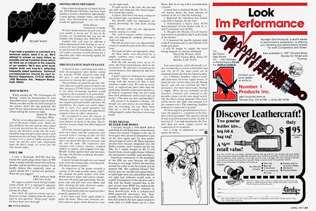
KEIHIN FIXED-VENTURI CARBURETOR WITH ACCELERATOR PUMP
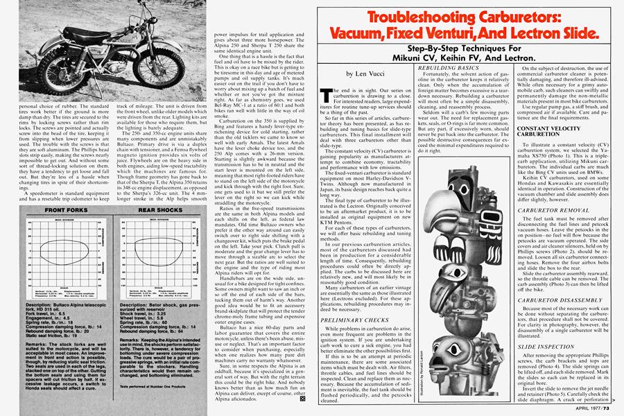
Popularly called a side-draft, the fixedventuri carburetor has been standard equipment on most Harley-Davidson V Twins. Earlier Harleys used either Tillot son dual-venturi or Bendix carburetors. Since late 1976, however, all models come equipped with the mechanically simpler Keihin version. We will use a 1977 Sports ter (Photo 16) to illustrate tuning pro cedures.
CARBURETOR REMOVAL
After removing the air cleaner cover, take out the hex bolt and three Phillips screws which secure the filter base (Photo 17). Disconnect the throttle cable and fuel line, and loosen the choke cable clamp.
Unscrew the two hex bolts which fasten the ignition switch and horn to the left side of the engine (Photo 18). Move this assembly out of the way. and remove the hex nuts and carburetor from the intake man ifold.
CARBURETOR DISASSEMBLY
Remove the vent hose from the float bowl. The bowl can be lifted off after four Phillips screws (Photo 19) are removed The accelerator pump rod and boot can be simply pulled off the bowl. Remove the two remaining screws securing the acceler ator pump cover. Lift off the cover, and remove the spring and diaphragm. Inspeci the diaphragm and 0-rings for cracks and brittleness, and replace if necessary.
After thoroughly cleaning the float bowl and pump cover, shake them. You should hear a slight rattle from the pump check balls. You should be able to draw but not blow through the accelerator pump nozzle (Photo 20) if it is sealing properly. Using
the float bowl vent hose, you should be able to blow but not draw through the fuel inlet hole of the pump cover.
If either of these ball checks is not operating properly, a blast of compressed air and a thorough cleaning in solvent should remedy the situation.
FLOAT INSPECTION
Remove the Phillips screw (Photo 21) which secures the float pivot pin, and lift off the float and needle. The neoprene needle tip should be smooth and straight. If grooved or deformed, the needle should be replaced.
JET LOCATION
Removal of the main jet allows the jet nozzle to be extracted. Pull off the rubber plug, and unscrew the pilot jet located beneath it (Photo 22).
Unscrew the idle mixture screw (Photo 23), and inspect its tip. If it’s not smooth and straight, replace it.
CARBURETOR REASSEMBLY
After its components are cleaned or replaced, the carburetor can be reassembled.
Place the needle on the float, slide the pivot pin into location, and replace this assembly on the carb body. Tighten the pivot pin retaining screw.
The floats must now be adjusted. With the carb inverted, measure the float level (Photo 24). It should be 14 mm to 16 mm (9/i6 in. to 5A in.). Adjustment is made by bending the metal tab which contacts the float needle.
Float drop must also be adjusted. Hold the carburetor in its normal position, and measure from the carb base to the bottom edge of the float (Photo 25). The distance should be 28 mm to 30mm (l-~/32 in. to 1/16 in.). Bend the outer tab on the float to adjust.
drop mm mm.
Replace the jet nozzle, main jet. pilot jet, and rubber plug. Place the accelerator pump rod and boot on the float bowl.
Make sure the large float bowl O-ring and small pump nozzle O-ring are in place. Engage the accelerator pump rod in its slot, and place the bowl in location. Install the three short float bowl screws, but do not tighten them.
Place the pump diaphragm on the float bowl, ridge-side down, followed by its spring. A small O-ring should be in place on both the float bowl and pump cover. Place the cover on the bowl, and install the three remaining screws. Evenly tighten all six bowl and pump cover screws, and replace the vent hose.
PRELIMINARY ADJUSTMENT
The accelerator pump limit screw' should be approximately 6 mm (% in.) from its stop (Photo 26). The pump duration spring should be in the center notch.
Turn the idle mixture screw' in until it lightly seats, then back it out one full turn.
CARBURETOR REINSTALLATION
Reverse the removal sequence to reinstall the carb on the bike, with one exception: Before replacing the ignition switch assembly, pull the choke knob out until the cable end is fully retracted. After the switch assembly is in place, push the choke knob in, guiding the cable end into position. With the choke fully open, tighten the screw, and check for full opening and closing.
The fuel line and air filter assembly should now' be replaced.
CARBURETOR ADJUSTMENT
Start the engine and warm it to operating temperature. Set idle speed to 800 rpm. Turn the idle mixture screw in until a drop in rpm is observed, then back it out until the engine is running smoothly. If necessary, reset the idle speed.
Test ride the machine, quickly opening the throttle at various engine speeds. The engine should pull smoothly in all gears, without stumbling.
If the bike misfires when the throttle is opened quickly, but runs well if the throttle is eased on, the accelerator pump probably needs adjusting. This is a deceptively tricky operation. Backing the pump limit screw' out causes more gas to be delivered during sudden throttle openings. This results in a decrease in fuel economy.
The position of the pump duration spring has no effect on volume of fuel delivered, but controls its rate.
Proper tuning, then, is a balance of three factors: accelerator pump volume, delivery rate, and economy.
For your normal riding habits, adjust the pump volume for the minimum delivery that still allows a smooth throttle response. The spring position may also be varied, in conjunction with a volume adjustment. Granted, it sounds complicated. But staying fairly close to the basic settings will most likely yield satisfactory results.
THE LECTRON CARBURETOR
In an attempt to devise a better mousetrap, one often comes up with a more complicated one. Encouragingly, the Lectron carburetor (Photo 27) demonstrates that just the opposite can be true. It is technically a slide-type carburetor, but its fuel metering system is truly unique. Its simplicity will become immediately apparent as its construction details are illustrated. A brief operational description and analysis will then be offered.
CARBURETOR SELECTION
Selection of a Lectron to be used as replacement for a more conventional carburetor is a basically simple matter. For most applications, Lectron size will be the same, or possibly one size (2 mm) larger, than the original. There is then only one component (metering rod) change necessary for broad adjustment of the carb.
SLIDE REMOVAL
The slide cover, secured by three Allen screw's, should be removed. The guillotine slide can then be extracted (Photo 28). The Lectron metering rod. locked into the slide by an Allen set screw, is easily adjusted or changed.
FLOAT INSPECTION
The float bowl (also available in transparent plastic) is secured by four Allen screws (Photo 29). The Lectron uses an independent float assembly (Photo 30). Adjustment is similar to Mikuni independent float carbs. The float lever is measured at the centerline of the carb (Photo 31). Height should be 25 mm (1 inch). Bend the tang on the float lever to make this adjustment.
Except for the conventional starting enrichment circuit, that’s about all there is to the Lectron carb.
REASSEMBLY
Replace the gasket and float bowl and tighten the four Allen screws. Feed the throttle cable through the rubber boot, carb top cover, gasket, and into the slide. Install the slide into the body, guiding the metering rod into place. Replace the three top Allen screws.
continued on page 112
continued from page 78
Very simple.
HOW (WHY) IT WORKS
A conventional slide carburetor utilizes a pilot air screw, pilot jet, needle jet, jet needle, and main jet. Interacting with each other, they provide the proper amount of fuel and air mixture required by the engine.
The Lectron has only one circuit, consisting of the special slide needle, called a metering rod, metering fuel through a passage to the float chamber. This passage is analogous to the needle jet in a conventional carburetor. The special taper of the metering rod, and its position in the jet passage, determines fuel flow for a given slide position. By adjusting the position of the metering rod in the slide, fuel/air mixture is varied across the entire rpm range. By installing a different metering rod, the fuel/air mixture can be tailored to the requirements of the engine at any point in the rpm range.
But this is theory. How is it actually applied to carb tuning?
TUNING THE LECTRON
We’ll assume you have purchased and installed a Lectron carburetor on your bike. Start the engine, warm it to operating temperature, then let it idle. Most likely the metering rod will need to be adjusted. After loosening the set screw, the rod is turned in (clockwise) to riehen the mixture, and out to make it lean. When proper idle is obtained, make a full throttle run. The engine should pull strongly. If pinging (detonation ) occurs, the mixture is too lean. If the engine is sluggish, make a plug check. A dark, sooty condition indicates excessive richness. In either case, a metering rod change is necessary. This basic procedure should suffice for most fourstroke applicatons.
If you have a two-stroke engine, this procedure still applies. Pinging indicates excessive leaness. But “four-stroking” (a regular, even misfire) would be an indication of richness. Additionally, a similar mid-range run should be made. The fuel requirements of a two-stroke differ in the mid-range from a four-stroke. Lectron provides a series of metering rods yielding a richer mid-range mixture. By varying metering rod types and position, the Lectron should satisfy even the most critical carburetion application.
OBSERVATIONS
Some enthusiasts and professionals swear by Lectrons. One of our staffers owns a Yamaha TT500 so equipped, and has nothing but praise for the Lectron carb.
Other not-so-enthusiastic cyclists sweat at Lectron carbs. A pro desert racer friend recently removed the Lectron from his TT500 in favor of a standard Mikuni.
When comparing the Lectron to the conventional slide on a purely technical basis, both plus and minus points are tallied.
The conventional carb allows the fuel mixture to be tailored precisely, in several stages, with minimal interaction. The Lectron, while a bit more tricky to set up, requires the adjustment or exchange of only a single component, the metering rod.
Primarily on these points, we would: a) recommend the Lectron for those who thoroughly understand engine induction requirements, and b) recommend a conventional carb for those whose knowledge and experience in carburetion is limited. Is our desert-racer friend an incompetent? No. His preference was for a design with which he is most experienced—a matter of confidence, if you will.
As the performance-oriented motorcyclist gains experience with and knowledge of Lectron carburetion, its popularity will definitely increase.
WHENCE HENCE
This wraps up the series on carburetion. Quite a few words have been penned on this simple concept of sucking wind.
In future issues of CYCLE WORLD, look for basic information on engine and chassis maintenance. We’ll provide you with a means of getting the most out of what you have—and let you save a buck in the process. I5l