Troubleshooting Carburetors: Rebuilding And Tuning Singles
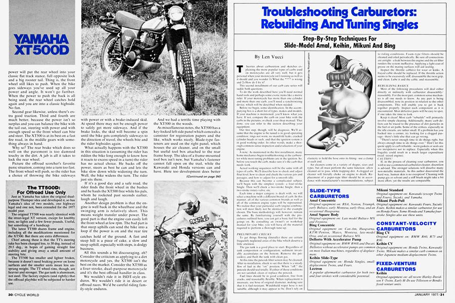
Troubleshooting Carburetors: Rebuilding And Tuning Singles
Step-By-Step Techniques For Slide-Model Amal, Keihin, Mikuni And Bing
Len Vucci
Theories about carburetion and sketches explaining the more popular types of carbs used on motorcycles are all very well, but it gets personal when your motorcycle isn't running as well as it should and you wonder 1) What the **** is wrong and 2) How do I fix it?
This second installment of our carb care series w ill tackle both questions.
To do the work described here you’ll need normal hand tools and perhaps some exotic items like a metric ruler. If your motorcycle has more than one cylinder and more than one carb. you'll need a synchronizing device, which will be described when needed.
Before we begin, some identification. In the accompanying box is a short list of types, makes and models. If your machine is mentioned, you'll know what you have. If not. compare the carb on your bike with the carbs in the pictures, or check your shop manual. That done, you can refer to the section describing your equipment.
Our first step, though, will be diagnosis. We’ll assume that the engine to be tuned is in good operating condition: rings not worn, no manifold leaks, cracked cylinder heads or such, and that the ignition system is in good working order. In other words, make a thorough common-sense inspection and evaluation of your engine.
A note: As mentioned in the first installment, many home mechanics begin troubleshooting at the carburetor while most tuning problems are in the ignition. So. before you touch the carb. make sure it's the carb that needs work.
Actual working sequences w ill be the same with all types of carbs. We’ll describe how to check and adjust float level, how to clean and check the various jets and passages, and how to adjust for a smooth idle.
Because this can become a complicated subject, we'll begin with the simplest system: a four-stroke Single. Then we'll check a two-stroke Single, then a two-stroke rotary-valve, etc.
Each time a major category is dealt with, we will select a machine w ith a different brand of carb. In this manner, all of the various common brands as well as all of the common engine types will be represented. We realize that your particular carb/engine combination will most likely not be identical to the example chosen. The basic methodology will, however, remain the same. By familiarizing yourself with the procedures outlined here, you can get a basic feel for the goings on. By consulting an owner's or workshop manual for your bike, you will have all the material required to perform a thorough tune-up.
PRELIMINARY CHECKS
To get things flowing (literally) there are certain frequently neglected areas of the bike w hich deserve a little attention.
The gas tank is a good place to start. Regardless of tank composition or configuration, sediment invariably accumulates on the bottom. Remove the petcock(s). and flush the tank with clean gas.
At this time the petcock filter screen may be cleaned. After re-installation, check to see that there is a steady flow of fuel in the “on" position. When “off." the petcock should seal totally. If either of these conditions are not satisfied, clean or replace the petcock.
Euel lines should be in good condition, free from cracks, and reasonably flexible. When replacement is necessary, use hose of original diameter, making sure that it is fuel-resistant. Windshield wiper hose is not suitable, although it may appear to be. Don't rely on elasticity to hold the hose onto its fitting—use a clamp at each end.
Air cleaners come in a variety of shapes, sizes and types, but all must perform the same function: allow cleaned air to pass, while trapping dirt. A clogged air cleaner will literally choke an engine to death. Replacement of a paper-type filter should be in accordance with manufacturer’s recommendations, subject to riding conditions. Foam-type filters should be cleaned and oiled periodically. Be sure all connections are airtight—a leak betw een the engine and the air filter renders the system ineffective. Applying a light coat of grease on the mating surfaces will aid sealing.
Inspect the throttle cable(s) for wear or kinks. A frayed cable should be replaced. If the throttle action seems to be excessively stiff, disassemble the twist grip, and clean. Lube it and the cable, and reassemble.
REBUILDING BASICS
Most of the following procedures will deal either directly or indirectly with carburetor disassembly/ reassembly. For the most part, common sense mechanics is all one needs to know. As any part is being disassembled, note its position in relation to the other components. This will enable you to get it back together properly. Inspect each component as it is encountered. Most defective parts w ill be easy to spot, if one takes the time to look.
Keep it clean! Most carb “rebuilds” will primarily involve simple cleaning. Additionally, many carb defects can be traced to the presence of dirt particles in the fuel or air paths. Some of the orifices, especially in the idle circuits, are rather small. If a problem has you backed into a corner, try looking for a clogged passage—there’s little else that can go wrong.
“There’s never enough time to do things right, but always enough time to do things over." Don't let this quote apply to carb rebuilds—worn gaskets or seals are too inexpensive not to replace. Especially when this frugality could result in a much larger expenditure (read: seized engine).
CA UTION!
If. in the process of cleaning your carburetor, you wish to use a commercial carburetor cleaner, discretion is advised. The stronger solutions will dissolve many non-metallic materials. As this author discovered the hard way. human skin is no exception! Cleaning with pump gas or solvent and a stiff brush might take a bit more effort, vet the results are comparable.
SLIDE-TYPE CARBURETORS
Amal Concentric
Original equipment on: BSA, Norton, Triumph, early Bultaco, early Montesa, early Ossa, and an occasional Husqvarna.
Amal Square Body
Original equipment on: Late model Bultaco MX and Frontera.
Bing Concentric
Original equipment on: Can-Am, Husqvarna, KTM / Pen ton, Maico, Montesa, late-model Ossa, and an occasional Bultaco MX.
Dellorto With Accelerator Pump
Original equipment on: BM W R90S and Ducati. Dellortos without accelerator pumps are common on most Italian machines, regardless of displacement.
Keihin Slide-Type
Original equipment on: Honda Singles, smalldisplacement Twins, and Fours.
Lectron
A popular aftermarket carburetor for both twoand four-strokes with considerable potential.
Mikuni Standard
Original equipment on: Kawasaki (except Twins and Fours), Suzuki, and Yamaha.
Mikuni Push-Pull
Original equipment on: Kawasaki Fours, Suzuki Fours. Keihin makes a similar carburetor for use on Honda Fours. Some Honda and Yamaha fourstroke Singles also use these units.
CONSTANT-VELOCITY CARBURETORS
Bing CV
Original equipment on: BMW R60, R75 and R 90.
Keihin CV
Original equipment on: Honda Twins, Kawasaki Twins. Mikuni makes a similar carb common on other Japanese medium-displacement Twins.
FIXED-VENTURI CARBURETORS
Keihin
Original equipment on: all recent Harley-Davidson V-Twins. Early H-Ds use Tillotson or Bendix fixed-venturi units.
Once the related details are taken care of. one can tackle the carburetor itself. Depending upon the age and condition of your bike, you may wish to make only minor adjustments, such as idle speed and mixture. The entire procedure will be presented in such a way that you should be able to determine which steps will be necessary.
KEIHIN SLIDE TYPE CARBURETOR/FOURSTROKE SINGLE
The simplest of engine to tune is the four-stroke Single. For this reason we have chosen the Honda XL 125 as our first example.
The procedures undertaken here will applv to virtually all types of engine/carb configurations. Once a thorough understanding of the simple systems is gained, the mysteries of more complicated set-ups w ill unfold quite readilv.
REMOVAL EOR INSPECTION
The carb on the XL 125 is secured bv two hex nuts and the air filter hose. (Photo 1) Once these are removed and the fuel line disconnected, the carburetor may be separated from the air cleaner hose and engine. Unscrew the ring from the top of the carb. This w ill enable you to remove the slide assembly (still attached to cable) from the carb bodv. which mav be set aside for now. Compress the slide assembly (Photo 2) to separate it from the cable
FLOAT INSPECTION
Removal of the float bowl is accomplished bv sliding off the retaining wire. This Keihin has brass floats which are removed bv sliding the pivot pin out (Photo 3). Shake the float. If any gas has leaked into either tank, replace the float assembly. Remove the float needle from its seat, and inspect the tapered end. If it is grooved badly, it could leak. This can be tested fairlv easily. Reinstall the float needle, floats and pivot pin. Connect the fuel line to the carb. and turn the petcock on. If the carb is in its normal upright position, a steady stream of fuel should come through the float valve. Now gently push up on the float until you feel the needle seat. (Photo 4) The floyv of fuel should cease. If it does not. replace the needle and seat assembly .
FLOAT LEVEL ADJUSTMENT
Once vou are satisfied that the floats and needle valve are fully operational, the float level mav be set. Angle the carb. allowing the float assembly to rest lightly on the needle valve. Measure the distance from the edge of the float to the carburetor surface. ( Photo 5) It should be 24mm for this carburetor. To adjust float height, the tab which rests directly on the valve needle can be carefully bent.
Float adjustment, if possible, for other carbs yvill be similar, except for actual dimensions. (We say if possible because some carb float set-ups are not adjustable.)
JET LOCATION
The main jet and pilot jet are show n in Photo 6. The pilot jet screws directly into the carb bodv. while the main jet. w ith baffle, is attached to the emulsion tube.
Besides holding the main jet. the emulsion tube is used to aid mixing of air and fuel. (In some carbs. the main jet holder also holds the needle jet. Examples of this configuration will be illustrated subsequently ). Note that there are numbers stamped on each of the jets, corresponding to their respective size. A higher number indicates a jet with a larger diameter orifice.
Take care w hen removing and replacing the jets, as a slight scratch in the orifice can alter flow characteristics. If a jet becomes obstructed with a particle of dirt, attempt to clear it bv blowing through it. The same
EXHIBIT A
holds true for anv passage in the carburetor itself. If this or a careful blast of compressed air fails, use a piece of copper (not steel) w ire to clear the passage.
SLIDE AND NEEDED INSPECTION
Bx carefully pushing on the needle, it and the retainer can be pushed out of the slide. Note that there is a horseshoe clip in one of the five slots of the needle (Photo 7). This can vary needle position, and will be elaborated upon subsequently . For now. roll the needle on the edge of a flat surface to insure that it is
straight. Also check that it is fairly smooth. A bent and/or badly scuffed needle should be replaced.
The needle jet. if xvorn bx a bent needle, should also be replaced. After removing the emulsion tube (Photo 8). the needle jet max be pushed out of the carb body. A short length of VK" w ooden doxy el is a suitable tool. Reinstall in a similar manner.
CABURETORE BODY
With its various components removed, the carb bodx can be inspected. The idle speed and mixture screws (Photo 9) should be taken out and cleaned. Do not interchange them, or their springs. Make as thorough a visual check of the carb passages as possible. Clean the bodx thoroughly, blowing air thru each passage.
REASSEMBLY
Once you are sure that the individual components are in serviceable condition, the carb max be reassembled. Check jets for tightness, and floats for level. If the gasket is in good shape, the float boxvl max be reinstalled.
Make sure the horseshoe clip is in its origin a I slot, and drop the needle back into the slide. Replace the needle retainer, making sure it is snug against the slide bottom. Slip the throttle cable through the threaded ring and carb top. and through the slide spring. Compress the spring, and at the same time hook the end of the cable into the slide slot. The slide assembly can now be inserted into the carb body. The slide cutaway should alxvays be a t the a i r filter side of the carburetor ( Photo 10). Attempting to insert it any other wax could scratch the slide. The slide assembly should literally drop right into place if it doesn't, check that the needle is positioned properly in its jet.
Snug the slide cover down, then twist the throttle a few times. The slide action should feel fairly slick.
Check that the 0-ring on the mounting flange is in good shape, then fasten the carb to the engine. Slip the air cleaner hose back on. and connect the fuel line.
Bx utilizing the adjustments on either end of the throttle cable, remove all but a slight bit of free plav. If the cable is too tight, the engine idle speed mav not he adjustable.
TUNING PROCEDURES
Noxx that the induction system is in good working order, we must tailor its operation to the requirements of the engine. A box stock engine may require little more than an idle adjustment. A slightly modified bike (aftermarket exhaust installed, for example) may need a jet change. Likew ise for a bike to be used at altitudes which varx greatly. We'll present only the basics here. This should suffice for most of your tuning needs.
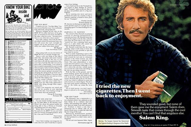
Exhibit A
Spark plug coloring should be similar to plug 3. Plugs 1 and 2 are lean. Plugs 4, 5, and 6 are progressively richer. Those with really radical equipment should consult a suitable aftermarket tuning manual.
Ideallv. a dynamometer facility is essential to extract maximum performance from any motorcycle engine. As few of us are that fortunate, other means of monitoring engine operation must be employed. One is seat-of-the-pants dyno testing, the other is plug reading. A combination of both is necessary to ensure reliable operation. Riding the bike will give a basicindication of tuning effects. Bx checking spark plug condition, one also has an objective means of assessing the actual combustion process.
Unfortunately, this may pose several problems. One phase of tuning requires the operator to ride his motorcycle at full throttle for a short period of time. This is possible for a small bore bike, especially if it is an off-road model. But if one has a large displacement road machine, speed is limited by both safety and legality. In this case, one has several options: l) Seek out a shop with a dyno. Final adjustment can be made under controlled conditions. 2) Operate the vehicle on a sanctioned race track. If you are building a hot street bike, for example, a few runs on a drag strip should get the tuning sorted out. 3) Run the bike at the maximum speeds at which it is normally operated. Most street bikes are jetted fairly accurately at the factory, so these speeds should be sufficient.
While these runs are being made, engine operation must be evaluated. Spark plug condition is one very useful indicator. The following tuning procedures combines plug reading xvith performance. For most four-stroke Singles of other makes, the methods outlined for our example bike should be directly applicable.
GETTING STARTED
Screw the idle mixture screw inward (clockwise) until it lightly seats. Then back it out one full turn. Turn on the gas. and after a I low i ng time for the float boxvl to lilt, check for anv fuel leakage. If all is dry. start the engine. It should fire right off. but if not. a recheck of xour xvork is in order. (Don't neglect the spark plug and ignition system.)
IDLE CIRCUIT ADJUSTMENT
When the engine has reached operating temperature. the idle circuit can be adjusted. Turn the idle speed screw in until the engine is idling at about 1200 rpm. Turn the idle mixture screw clockwise until the engine slows, noting its position. Noxx turn the screw in the opposite direction so that the engine again slows. Set the mixture screw halfway between these two extremes. Now adjust the idle speed screw for about 1000 rpm.
HIGH SPEED ADJUSTMENT
Due to interaction between different carb circuits, adjustment of the high speed (main jet) circuit is usually performed first. Because it is necessary to check spark plug condition, a fresh plug of the proper heat range should be installed.
As mentioned previously, a high speed run must be made. As conditions allow, run the engine at wide open throttle fora brief stretch. De-clutch and shut the engine down at the end of the run. Do not downshift cm use the engine for compression braking.
Pull the plug, and examine the porcelain around the center electrode. If the mixture is correct, the porcelain should be tan in color. (See the accompanying photo chart for representative plug coloring).
A darker tan. brow n, or sooty black indicates a rich condition. The main jet size should then be decreased.
A white, grey or very light tan indicates that the engine is running lean, a potentially damaging condition. In extreme cases, the porcelain can be blistered, and the electrodes melted.
Another indication of lean mixture sometimes is present: detonation. Also called pinging, detonation is caused bv excessively hot combustion chamber temperatures. To correct this lean condition, a larger main jet must be installed.
When re-jetting for mixture correction, jets one to two sizes different should be tried, until the proper plug reading is obtained. Keep in mind that it is better to be slightly rich than excessively' lean.
MID-RANGE ADJUSTMENT
A similar method can be used for mid-range mixture adjustment. By running at half-throttle, then shutting down, a plug reading may again be taken. Again, a tan color indicates correct mixture.
To change mid-range mixture proportions, the needle position is varied. To enrichen the mixture (i.e. plug color is too light), the needle is raised in the slide. Note that in order to raise the needle, the horseshoe clip must be put in a lower needle groove.
If the mixture is rich (i.e. plug color is too dark ). the needle should be lowered in the slide. The horseshoe clip is then placed higher on the needle.
If a change in needle position does not correct the mixture entirely, the needle jet max have to be changed. As with main jets, a larger jet size enrichens. a smaller jet size leans the mixture.
In some cases, the needle itself max haxe to be changed.
Understandably, there might be some confusion as to which components should be changed. If varying the needle position doesn't correct the problem, and one has doubts, consult tin owners/workshop manual for exact procedure.
I. O W SPEED CIRC UI T A DJ US TM ES 7
From idle speeds to about N throttle, mixture is controlled by the pilot jet. Without lugging the engine, motor around in the low gears. The engine should pull smoothly with the throttle just off idle. If it does not. there are several methods which can be used to determine whether the mixture is rich or lean.
Initially, engage the choke or starter circuit slightly, enrichemng the idle mixture. If the bike's response is better, the idle circuit is too lean. Conversely, if this just aggravates the idling problem, the carb is too rich.
The idle mixture screw max also be used to check low speed mixture, although its effects will be limited. Turning this screw clockwise richens the mixture: counterclockwise is leaner.
The spark plug may also be checked for fouling. As there is little heat buildup xxltile idling around, a dark sootx deposit indicates that the idle circuits are excessixelx rich.
An oilv. xvet deposit could mean that the piston rings and/or valve seals could be worn. When the throttle is blipped at idle, light grevish-blue exhaust smoke indicates oil consumption. A rich condition, on the other hand, xxill produce a darker, sooty smoke from the exhaust.
If the idle mixture requires correction, the pilot jet is changed. As xx ith the main jet. orifice size corresponds to jet number. Once the correct jet is installed, idle mixture and speed should also be re-set.
IDLE TO MID-RASGE TRAS SITIOS
From about N to O throttle, the amount of slide cutaway also influences air/fuel mixture. As the throttle is rolled on from idle, the engine should respond smoothly as rpm increases. This is more critical for two-stroke engines. The stock cutaxvax in a four-stroke carb xxill rarelx need changing. For this reason, cutaway xxill be elaborated upon in the section on twostroke tunin«.
SUMMARY OE PROCEDURES
At this point, one should have a grasp on most of the details necessary for tuning a four-stroke Single. As an aid to understanding, here’s a brief summary:
1) Ensure that engine is in good working order: Compression, ignition and valve train okay.
2) Inspect, clean and repair fuel system, including fuel tank, petcocks. fuel line and cables.
3) Remove carburetor; disassemble and clean thoroughly. Replace anx worn parts, set float level, reassemble and reinstall.
4) Adjust mixture for entire rpm range:
a) Idle: Mixture and rpm screws
b) High-speed: Main jet
c) Mid-range: Needle and needle jet
d) Reset idle.
For the neophyte, the abundance of information necessary for tuning may seem overwhelming. New experiences are often that way. As one becomes familiar. one w ill have a much easier time of it. With that in mind xve'll now progress to two-stroke procedures.
In operation, there is very little difference betxxeen four and two-stroke carburetors. Because of the nature of the mechanically simpler two-stroke, however, mixture requirements are critical. Additionally, a means of lubricating the “bottom end" of the engine must be proxided. This is accomplished b\ mixing a small amount of oil w ith the gasoline. This “oiled" fuel is then drawn into the engine, and subsequently burned. There are two basic types of lubrication: automatic injection, and premix. The first type of two-stroke to be discussed is of the premix (non-automatic injection) variety.
AMAL SQUARE-BODY SLIDE CARBURETOR/TWO-STROKE SINGLE
We have chosen the Bultaco Frontera as being representative of mans two-stroke Singles. It is equipped xxith an Antal carb. and is of the premix variety. B\ this is meant that oil is added directly to the gas in the fuel tank. This gas/oil mixture is then admitted into the carburetor. Differences in operation and tuning methods front those previouslx outlined xx ill be noted as encountered.
REMO l AI. EOR ISSPECTIOS
This carb is “spigot mounted" being secured bx hose clantps on both engine and air filter sides. (Photo II). Remove the fuel lines, then loosen the two hose clamps securing the engine. The carb ntav noxx be worked free. Unscrew the slide cover, and separate the carb front the slide assembly. Compress the slide spring, letting the cable end protrude front the slide bottom (Photo 12). Allow the cable to be retracted through the smooth hole, and the slide assembly can be separated. Inspect the slide and needle, making sure that each is in good condition.
FLOAT INSPECTION
Remove the fuel inlet assembly from the float bowl. This is accomplished by unscrewing the "banjo" bolt with fiber yvasher. "banjo", and filter. (Photo 13). (Note: This is a "double-necked banjo"!) Remove the four hold-down screws, keeping the how l and the carb together. Turn the carburetor so it's in an upright position, and lift the carb body off the bowl. The float assembly will remain in place (Photo 14). Note that this float is of hollow nylon construction, yvith no adjustment provision. Inspect it for leaks, then examine the float needle. It has a neoprene tip. and should seal tightly. To test for proper operation, reassemble the float chamber, including fuel inlet assembly, and connect the fuel lines. Hold the pivot pin down yvith two fingers, then turn on the fuel petcock. Fuel should partially fill the bowl, then cease to flow. (Photo 15). If the bowl overflows, the needle is not seating properly. C heck for foreign matter and/or a deteriorated needle tip. Clean or replace as necessary . 16. The pilot jet is located in the float bowl.
JET LOCATION
The pilot jet is. in this carburetor, located on the float bowl (Photo 16). It can be carefully removed with a small screwdriver.
The main and needle jet assemble is on the carb bod\. It has three individual components: main jet. jet holder, and needle jet (Photo 17 A assembled. 17 B disassembled).
CARBURETOR BODY
Remove the idle mixture and speed screws. Note that each has an O-ring for sealing. Inspect them for cracks or wear, and replace if necessary. When reinstalled. the O-rings should be greased to prevent damage.
The starting circuit assembly can be removed as a unit, using a hex wrench. Inspect the neoprene seal on the end of the plunger, noting that it can be removed from its shaft (Photo 18). Avoid scoring the plunger when reassembling, as this could cause it to bind.
The inlet or air horn is held on by two screws. Removal of the horn allows one to inspect the various jet air intakes (Photo 19).
REASSEMBLY
Once you are satisfied that the carb components are clean and in good working order, this puzzle can be put back together.
Install the starter circuit assembly. Make sure it moves freely in each direction, and that it will stay in either an open or closed position.
Replace the air horn, using a dab of Loctite on each screw.
Install the main and needle jet into the jet holder, and replace in the carb body .
Place the needle into the valve, and drop the float and pivot pin into the bowl. Make sure that the tab on the float engages the slot of the valve needle. With the pilot jet m place, and a good gasket used, the carb body can be placed on top of the float bow l. Replace the four screws and snug them down. Replace the fuel inlet assembly on the float bowl, keeping the banjo parallel to the bow l while tightening. Note that removal of the float drain plug also gives access to the jet assembly . This makes on-the-bike jetting much easier.
With the horseshoe clip installed, drop the needle into the center hole in the slide. Place the retaining discover the needle, tab down, so that the smooth hole is visible. Here things get a little tricky ! Place the spring in the slide on top of the disc. With the throttle cable adjusted to y ield the most slack, feed the cable thru the slide cover. Noyv. compress the spring. With needlenose pliers, feed the cable through the hole in the slide (Photo 20). Push the cable end over so it locks in place. The needle retaining disc now must be turned so that the tab hooks over the cast rib on the slide bottom, effectively locking the cable in place. Don't feel bad if this portion of reassembly becomes frustrating you w ill have had plenty of company.
The slide assembly can now be dropped into the carb body , and the cover snugged down. Don't become overambitious here being plastic, the cover could crack if overtightened.
Reinstall the carb. tighten the hose clamps, and adjust the throttle cable. Remember to leave a slight bit of free play in the cable.
Reconnect the fuel lines, turn on the petcocks. and check for fuel leakage. If all is dry. the tune-up can begin.
TUNING PROCEDUERS
Although mixture requirements differ between two and four-stroke engines, methods of obtaining the proper state of tune w ill be similar. There are. however. several important differences. One important thing to remember is that two-strokes are generally fussier about their fuel diets. An excessively lean condition may result in heat seizure, while being too far on the rich side w ill foul plugs. In other words, you have to pay close attention w hen tuning a two-stroke.
GETTING STARTED
Turn the idle mixture screw in until it lightly seats, then back it out a turn. Start the engine, and w arm it to operating temperature. If the engine fails to start, or runs extremely poorly, recheck your work to include ignition operation and spark plug.
IDLE CIRCUIT ADJUSTMENT
Run the idle speed screw in so that the engine is running at a fast idle. Turn the mixture screw clockwise until the engine begins to falter. Then back it out to a point where the engine is running smoothly. Readjust the idle speed for a normal idle.
HIGH SPEED JET ADJUSTMENT
Make a full throttle run up through the gears, keeping the revs fairly high. The engine should pull strongly on the top end in all gears. If the engine is running too rich, it will misfire on alternate revolutions. In addition to power loss, this will produce a characteristic “four-stroking” sound. Reduce the size of the main jet one step at a time until the engine runs strongly without four-stroking. The mixture, at this jetting, will he just slightly rich. For all applications except all-out racing, this is the place to he.
If. on the other hand, your carburetion tends to be lean, a potential for heat damage exists. Although the engine will pull strongly, it will usually give a warning in the form of detonation (pinging). If the ignition timing is ok and pinging remains, the mixture is definitely too lean. The main jet size should be increased. following one or both of the following procedures. Increase jet size one step at a time until pinging ceases. This will probably leave the mixture a bit too lean. To be safe, increase the jet size until fourstroking occurs, then drop back one size. The other method is reading the plug. You have to be careful here. Unlike four-stroke engines, two-strokes can be running properly, yet have plug colors which might not seem to be correct. This is due to the lube oil present during combustion. Plug color will be darker, depending on several factors:
A. Pre-mix ratio. Increasing or decreasing the amount of oil in the gas will cause respectively more or less color change.
B. Oil type. The amount of sy nthetic oil necessary for proper lubrication is typically half that of petroleum or castor-base oils. However, some synthetics (e.g. Bel Ray MC-1) will color the plug brown-black and give the porcelain a glazed appearance.
21.
The carburetor on the Kawasaki KD 125 is concealed beneath the crankcase cover. Therefore, unless you are an experienced plug reader, we advise you to check plugs mainly for reference purposes.
MID-RANGE ADJUSTMENT
From VA to U throttle, mixture is mainly determined by the needle and needle jet. Make a half throttle run to check mixture. If pinging occurs, raise the needle a notch at a time until it ceases. If the engine fourstrokes. the mixture must be leaned. In this case lower the needle in the slide.
If needle adjustment does not provide enough range, the needle jet should be changed. When trying different needle jets, the needle should be set in the center position to allow for fine tuning later on.
IDLE CIRCUIT ADJUSTMENT
Mixture adjustment from idle to '/s throttle are made using the idle mixture screw and. if necessary, a pilot jet change. The idle circuit can be checked in the same way as it yvas in the four-stroke section. If the throttle is opened from idle, the engine should pull smoothly. If it dies abruptly .it's probably too lean. As a check, engage the choke or starting circuit slightlv to enrichen mixture. Open the throttle again. If better results are obtained, the idle circuit must be enrichened.
If engaging the choke makes matters worse, the carb is too rich and must be leaned.
Initially, adjust the idle mixture screw. Clockwise enrichens. counter clockwise leans. If proper response is not attainable w ith the screxv set from Vi to 2 Vi turns out. the pilot jet must be changed.
LOW SPEED ADJUSTMENT
Using the detonation/four stroking method, check engine operation in the '/» to VA throttle range. If adjustment is necessary, the slide must be changed.
If the mixture is too rich. i.e. the engine is fourstroking and loading up. a slide w ith a larger cutaway can be installed. This allows more air to pass, leaning the mixture.
If the mixture is too lean, and detonation is heard, install a slide with less cutaway. This slide enrichens the mixture bv allow ing less air flow.
Most slides will have the cutaway size stamped on the bottom so you can easily obtain the correct size. The numbers represent sixteenths on an inch. A “4" would be 4/16 or one quarter inch. The slide shown is a “25”. representing 2.5 times one sixteenth inch or 5/32 inch.
Unless other carb or engine changes have been made, the slide will most likely have a useable cutaway. A slide change, because of the inconvenience and expense involved, should be your last resort xvhen adjusting mixtures.
SUMMARY OF PROCEDURES
As you have probably noted, two-stroke tuning follows essentially the same pattern as does four-stroke tuning. An important first step is to get things mechanically straight and clean. Then adjust for proper mixture. starting w ith the high speed circuits and working back. Recheck all procedures for added confidence and vour bike should be in an excellent state of tune.
MIKUNI SLIDE CARBURETOR ROTARY VALVE TWO-STROKE
The KD 125 is representative of manv two-stroke rotary-valve engines. It utilizes a Mikuni carburetor, fully enclosed on the right side of the engine case (Photo 21). It is also of the auto injection lubrication varietv. An oil pump is connected by cable to the throttle. As the throttle is varied, so is the amount of oil provided for lubrication. The obvious advantage here is that the pre-mix oil hassle is eliminated.
22.
With the cover off, the carburetor can be seen.
CARBURETOR REMOVAL
Removal of the choke knob and four hex bolts will allow the top boot to be slid back. The carburetor cover can then be taken off after the five Phillips screws are removed (Photo 22). Disconnect the fuel line, and pull the carburetor straight out. The float chamber vent and idle screw boot are then separated from the carb.
Unscrew the slide cover ring separating the carb body from the slide assembly. The slide assembly is separated from the cable in the same manner as shown in the Bultaco Amal segment. Inspect the slide and needle for wear and set aside.
ELOA T INSPECTION AND A DJUSTMENT Four screws secure the float bowl, and may be removed. The float valve should be inspected and tested as was the Keihin float on the XL 125.
Float level will be correct if the float is parallel to the carb as it is held upside down (Photo 23). Bend the metal tab which contacts the valve to set level.
JET LOCATIONS
The main jet and holder, screwed into the float bow l, are easilv removable (Photo 24). The needle jet in this carb is part of the fuel mixing tube. It is held in place by an O-ringed fitting. By unscrewing this fitting, the needle jet can be taken out through the slide cavity (Photo 25). Note that the jet has an indexing slot to maintain correct alignment.
The pilot jet is located in the carb body, and is removed with a small screwdriver (Photo 26). The idle speed screw is in the conventional location (Photo 27). but note the location of the idle mixture screw. Each of these screws is also retained by a compression spring.
CARBURETOR BODY INSPECTION
The starting enrichment assembly is similar to the Amal's and removable with a hex wrench.
Make sure that the carburetor body is clean and the passages clear in preparation for reassembly.
CARBURETOR REASSEMBLY
Replace the individual components in their proper locations. Lubricate the O-ring on the needle jet retainer (use a little oil or grease) and replace the float bowl. Reconnect the slide assembly to its cable, then reinstall it in the carb body. Attach the float chamber vent and place the boot over the idle speed screw.
Clean the rubber spigot, then slide the assembled carburetor back in place. Reconnect the fuel line, turn on the gas and check for leaks. If dry. the carb may now be adjusted.
TUNING PROCEDURES
Methods and adjustments for the KD125 are identical to those of the Bultaco. with the following exceptions: (what would a rule be without exceptions?)
1. Once the idle mixture is adjusted, the carb cover and top boot should be replaced. The operatidnal tests must be conducted with the complete intake system, including air cleaner, in place.
2. As idle speed is the only externally accessible adjustment, the side cover has to be removed and replaced for each jet change. Similarly, the top boot must be pulled if access to the slide or needle is desired.
Due to the automatic injection unit, the effects of lube oil on plug coloring is less than on premix engines. Depending on oil type and pump setting, the plugs may look nearly as clean as on a four-stroke. Even so. the detonation/four-stroking method is still a better test than plug reading for optimum fuel mixture.
OIL PUMP ADJUSTMENT
Utilizing the adjuster at the twist grip, remove all but a bit of throttle cable play. Remove the three Phillips screws and countershaft sprocket cover (Photo 28). The oil pump cover, held on by one additional Phillips screw, may then be removed.
With the throttle released, inspect the oil pump lever ( Photo 29). The mark on the lever should align with the corresponding mark on the lever stop. Adjust the pump cable if necessary. Work the throttle several times. The two marks should still be aligned at zero throttle opening. Now replace both pump and countershaft covers to complete the tune-up.
SUMMARY OE PROCEDURES
Described in detail, w ith references to prior carburetor treatment, tuning the K.D125 might seem a formidable task. A brief recap might help you when sitting down to get organized:
1. Perform preliminary cleaning and inspection.
2. Remove carburetor from engine.
3. Disassemble carburetor, clean, set float level, reinstall.
4. Set idle, replace covers, set jetting.
5. Adjust oil pump.
With the information on the K.DI25 tuning still fresh (we hope) in your mind, we’ll now proceed to the last carburetor system for this month’s installment.
(Continued on page 78)
Continued from page 37
BING SLIDE CARBURETOR ROTARY-VALVE TWO-STROKE
To round out this collection of carb/engine combinations. we have chosen the Can Am 125. This is a rotary valve engine, like the Kawasaki KD 125. but the carburetor is mounted externally (Photo 30). Actual tuning procedures will be identical to those used on the Bultaco Frontera.
CARBURETOR REMOVAL
As the carb is spigot mounted, loosening the hose clamps allows it to be removed. Disconnect the fuel line, then remove the slide assembly by unscrewing the two hold down screws.
FLOAT ADJUSTMENT
Slip the retaining w ire off the float bow l, w hich can then be removed. Inspect the floats and needle valve. Note that the pivot pin is a press tit and must be tapped out. After reassembly, the float level can be checked. Place the carb on the air cleaner inlet, and measure from float to base (Photo 21). It should be 25mm or 1 inch.
JET LOCATION
The main jet screws into its holder (Photo 32) which also retains the needle jet. The pilot jet is located adjacent to the main jet.
CARBURETOR BODY
All passages in the body should be checked for obstructions. The idle screws (Photo 33) should be removed and cleaned. Also check the tickler. It should operate without binding and it should retract completely.
REASSEMBEY
Once all components are inspected and cleaned, the carburetor can be reassembled. Ensure that the jets are tight and that float level is correct before the float bow l is replaced.
Fasten the slide assembly to the cable and insert it into the slide body. Tighten the two slide cover hold down screws, and the carb is reads for reinstallation.
OIL PUMP ADJUSTMENT
By removing the left crankcase cover, access to the oil pump is gained (Photo 34). l.ike the KD 125. the cable is adjusted so that the marks on the lever and case are aligned. That done, replace the cover.
TUNING PROCEDURES
As the photos have shown, the internal components of the Bing carb are quite similar to those of the Bultaco Amal. For this reason, the procedures for tuning the Amal can be applied. There is. however, one additional bit of information which will be useful. Occasionally, for racing, the oil pump cable on Can Ams is removed and the pump lever is wired in its maximum position. This increases engine lubrication at all partial throttle openings. If vour bike is set up this way. spark plug color w ill be the same as on a premix model.
That just about takes care of Singles. Carb tuning isn't that hard, eh? Read all the instructions first, keep everything clean and in order, and carb tuning becomes something the owner can do and do well.
And if you’re the owner of a Multi, read this article so you can deal with several of these individual pieces. Persuading them to work together is even easier than persuading them to work right. More on that next month.