Troubleshooting Carburetors: Rebuilding And Tuning Twins And Triples
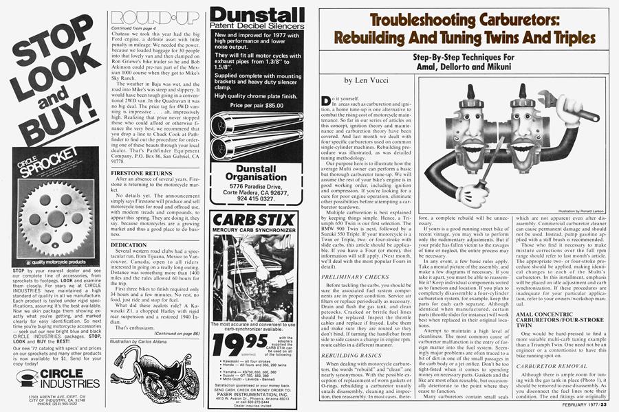
Troubleshooting Carburetors: Rebuilding And Tuning Twins And Triples
Step-By-Step Techniques For Amal, Dellorto and Mikuni
Len Vucci
Do it yourself. In areas such as carburetion and ignition, a home tune-up is one alternative to combat the rising cost of motorcycle maintenance. So far in our series of articles on this concept, ignition theory and maintenance and carburetion theory have been covered. And last month we dealt with four specific carburetors used on common single-cylinder machines. Rebuilding procedure was illustrated, as was detailed tuning methodology.
Our purpose here is to illustrate how the average Multi owner can perform a basic but thorough carburetor tune-up. We will assume the rest of your bike’s engine is in good working order, including ignition and compression. If you’re looking for a cure for poor engine operation, eliminate other possibilities before attempting a carburetor teardown.
Multiple carburetion is best explained by keeping things simple. Hence, a Triumph 650 Twin is our first selection. The BMW 900 Twin is next, followed by a Suzuki 550 Triple. If your motorcycle is a Twin or Triple, twoor four-stroke with slide carbs, this article should be applicable. If you have a Four (or more), this information will still apply. (Next month, we’ll deal with the most popular Fours in detail).
PRELIMINARY CHECKS
Before tackling the carbs, you should be sure the associated fuel system components are in proper condition. Service air filters or replace periodically as necessary. Drain and flush the gas tank, and clean petcocks. Cracked or brittle fuel lines should be replaced. Inspect the throttle cables and replace if frayed. Lube them and make sure they are routed so they don’t bind. If turning the handlebar from side to side causes a change in engine rpm, route cables in a different manner.
REBUILDING BASICS
When dealing with motorcycle carburetors, the words “rebuild” and “clean” are nearly synonymous. With the possible exception of replacement of worn gaskets or O-rings, rebuilding a carburetor usually entails disassembly, cleaning and inspection, then reassembly. In most cases, therefore, a complete rebuild will be unnecessary.
If yours is a good running street bike of recent vintage, you may wish to perform only the rudimentary adjustments. But if your pride has fallen victim to the ravages of time or neglect, the entire process may be necessary.
In any event, a few basic rules apply. Take a mental picture of the assembly, and make a few diagrams if necessary. If you take it apart, you must be able to reassemble it! Keep individual components sorted as to function and location. If you plan to completely disassemble a four-cylinder carburetion system, for example, keep the parts for each carb separate. Although identical when manufactured, certain parts (throttle slides for instance) will work best when replaced in their original locations.
Attempt to maintain a high level of cleanliness. The most common cause of carburetor malfunction is the entry of foreign matter into the fuel system. Seemingly major problems are often traced to a bit of dirt in one of the small passages in the carb body or a jet orifice. Don’t be too tight-fisted when it comes to spending money on necessary parts. Gaskets and the like are most often reusable, but occasionally deteriorate to the point where they cease to function.
Many carburetors contain small seals which are not apparent even after disassembly. Commercial carburetor cleaner can cause permanent damage and should not be used. Instead, pump gasoline applied with a stiff brush is recommended.
Those who find it necessary to make mixture corrections over the full rpm range should refer to last month’s article. The appropriate twoor four-stroke procedure should be applied, making identical changes to each of the Multi’s carburetors. In this installment, emphasis will be placed on idle adjustment and carb synchronization. If these procedures are inadequate for your particular application, refer to your owners/workshop manual.
AMAL CONCENTRIC CARBURETORS/FOUR-STROKE TWIN
One would be hard-pressed to find a more suitable multi-carb tuning example than a Triumph Twin. One need not be an engineer or a contortionist to have this bike running spot-on.
CARBURETOR REMOVAL
Although there is ample room for tuning with the gas tank in place (Photo 1), it should be removed to ease disassembly. As you disconnect the fuel lines note their condition. The end fittings are originally crimped on, and are prone to leak with age. New tubing can be fitted using small hose clamps.
Remove the banjo fittings and filters (Photo 2) being careful not to perforate the filter screens.
Because the two carburetors are identical except for idle screw location, only the right-hand carb disassembly/reassembly is illustrated.
The slide assembly can be extracted after removing the two Phillips-head screws which secure the slide cover. The carburetor body, held on by hex nuts and steel and rubber washers, can then be removed.
FLOAT INSPECTION
The float bowl drain plug should be unscrewed, and the fiber washer inspected.
Remove the two Phillips screws securing the float bowl, then lift the body oif the bowl. The float, pivot pin, and needle valve will remain intact (Photo 3). When shaken, the float should be empty of fuel. Presence of even a small quantity of liquid in the float indicates leakage, and necessitates replacement.
Inspect the float needle for signs of wear. A groove worn around the needle tip may indicate the need for replacement. To test for proper operation of the valve, reconnect the fuel lines to the float bowl, and reinstall the float assembly and drain plug. As fuel is allowed to flow to the bowl, it should reach a certain level and cease to flow (Photo 4). If the bowl fills and slowly overflows, replace the needle valve.
JET LOCATION
The pilot jet (Photo 5) screws into the carb body. Some Amal concentrics use a pressed-in pilot jet which is not removable.
The main jet is located on the jet holder. By removing the jet holder, access to the needle jet is gained (Photo 6).
SLIDE AND NEEDLE INSPECTION
Separate the slide from cable by compressing the slide spring and shift the cable-end position. This allows the needle to be withdrawn. Note the position of the retaining clip if it is removed. Check that the needle is smooth and straight. Replace the needle and the needle jet if signs of wear are evident.
This carburetor has no additional choke slide. Although they were original equipment on most Triumphs, the slides were removed. They were rarely used, even in winter. If your carburetors have chokes, be sure the cables are in good condition and the slides retract fully.
CARBURETOR BODY
Remove the idle mixture and speed screws (Photo 7) and inspect the O-rings which should be free from nicks or cracks. After applying a bit of oil or grease to prevent chafing, they should fit snugly when the screws are replaced.
The O-ring which seals the carb flange and manifold should be in serviceable condition. A leak here is potentially destructive.
Clean the body with solvent or gas, and blow through all passages to clear any debris.
REASSEMBLY
Now that the individual components are clean and in good working condition, the carburetor can be reassembled.
Install the main and needle jets in the jet holder, and snug this assembly onto the carb body. Replace the pilot jet.
Drop the float needle on its seat, and replace the float and pivot pin. Make sure the tab of the float engages the slot in the needle.
Using a serviceable gasket, place the carb body on the float assembly. Replace and tighten the hold-down screws.
If individual fuel lines and clamps are being used, the banjo fitting, filter, and bolt with fiber washer may be reinstalled. Replace the drain plug. With O-ring in place, mount the carburetor on the manifold flange. A rubber washer, steel washer and nut are placed on each stud. Alternately tighten each nut until seated, then replace the air filter hose.
Place the slide cover, spring, and throttle slide on the cable. Lock the cable into place on the slide. Drop it into the carb body, cutaway to the rear. Lift the spring up and off to the side, (Photo 8) and drop the needle into place. Tighten the cover.
After both carburetors are checked, replace fuel lines and gas tank.
Before the tune-up begins, check the balance hose connecting the two intake manifolds, and replace if necessary.
Turn on the gas. If all connections and surfaces remain dry, the engine can be started.
TUNING PROCEDURES
Now the carburetors are in good working order and must be adjusted. The idle will be coarsely set, and operation of the various circuits checked. Final idle adjustment and synchronization completes the procedure.
GETTING STARTED
Turn the idle mixture screws in (clockwise) until they lightly seat, then back them out two turns.
Turn the idle speed screws out (counterclockwise) until resistance of the slides pressing on the screws is no longer felt. (There must be a slight bit of free play in each throttle cable.) At this time both slides will be bottomed in their bores. Run each screw back in to the point where contact against the slide is again felt. Tighten each screw an additional turn.
Start the engine. Although the idle speed may not be correct at this point, run the engine until it is at normal operating temperature.
Turn each idle speed screw an equal amount, adjusting engine speed to about 1000 rpm. Run one idle mixture screw in until the engine begins to lose rpm, then back out until it runs smoothly. Repeat for the other idle mixture screw. Readjust idle speed to 800 rpm.
CABLE ADJUSTMENT
Adjust the throttle cables so a slight, but equal, amount of free play is felt in each. Gently open the throttle until the slide(s) top out. Grasp the throttle cable just above either carb and pull. Repeat for the other carb. If the throttle cables are adjusted properly, neither will have free play at this point.
Release the throttle fully, and open it just to the point where the initial free play is eliminated. Again neither cable, if pulled, should have free play.
OPERATIONAL ADJUSTMENTS
The operating circuits of the carburetor will most likely not need alteration. But if poor running is experienced at engine speeds from one-quarter throttle on, adjustment is necessary. Final adjustments can now be made.
CARBURETOR SYNCHRONIZATION
There are several methods of syncronization, one of which you have already performed by adjusting the cables. Two methods of greater accuracy will be given, one of which employs an aftermarket vacuum measurement device.
RPM DROP SYNCHRONIZATION METHOD
With the engine at operating temperature, and previous operations performed, the carbs should be close to sync. Disconnect either spark plug lead, and ground it with a short wire to prevent coil damage (Photo 9). (An alternate method would be to ground the ignition at the breaker points.) Restart the engine, and readjust the idle mixture screw for maximum engine speed and smoothness. Note the rpm, then shut the engine off.
Replace the loose plug wire, and ground the opposite plug lead. Restart the engine, and adjust the idle mixture screw of the firing cylinder for maximum rpm and smoothness. Adjust its idle speed screw for the same rpm as the opposite cylinder.
With both plug wires connected, the carbs will be in sync. Reset the idle if necessary, repeating the previously stated procedure. Check and readjust cables if necessary.
VACUUM MEASUREMENT DEVICES
Vacuum in the intake manifolds is a function of fuel/air mixture flow. By monitoring intake vacuum the carburetors can be adjusted for equal flow.
There are several devices on the market for measuring vacuum. We used a device called “Carb Stix” (Photo 10). Operation is simple. A length of surgical tubing is fastened at one end to the intake manifold. The other end is connected to a thin glass tube, at the bottom of which is a reservoir of mercury. When the engine is running, manifold vacuum draws the mercury up the tube. The device can sync up to four carbs at a time. Adjustment is correct when the level of mercury in each tube is equal.
VACUUM SYNCHRONIZATION
With the engine idle coarsely adjusted, fasten a “Carb Stix” tube to each intake balance tube fitting. Adjust each idle mixture screw for maximum rpm and smoothness. Using the idle speed screws, adjust engine speed to 800-900 rpm. At the same time, watch the levels of mercury in the “Carb Stix,” and keep them as equal as possible (Photo 11). When the proper rpm is attained and mercury levels are equal, the carburetors are synchronized. Replace the balance hose, and repeat the cable adjustment procedure if necessary.
PROCEDURAL SUMMARY
1. Thoroughly inspect associated fuel system components including cables, tank, air filters, and hoses.
2. Refurbish carburetors; replace worn or damaged components.
3. Reinstall carburetors and hardware, and make preliminary mechanical adjustments.
4. Run engine to operating temperature, and coarsely adjust idle and cables.
5. Run engine over full rpm range to check operating circuits.
6. Finely tune idle circuits and synchronize carburetors.
DELLORTO CARBURETOR WITH ACCELERATOR PUMP/ FOUR-STROKE TWIN
Although not very common on bike carburetors, several manufacturers utilize accelerator pumps. The Dellorto slide “pumper,” as used on pre-1977 “S” series BM Ws (Photo 12), is illustrated here.
CARBURETOR REMOVAL
Utilizing a 10mm hex wrench, remove the starter circuit plunger, and leave it attached to the cable (Photo 13).
Loosen the slide cover screws and remove the slide assembly from its bore. Compress the spring, and remove the needle and clip from the slide. Free the cable end and remove the slide. Check the needle for wear, and note the position of the retainer clip.
Loosen the hose clamps that secure the plastic air filter elbow, and remove it. Disconnect the fuel line, and loosen the spigot clamp to remove the carburetor.
FLOAT INSPECTION
Removal of the hex drain plug allows the float bowl to be removed (Photo 14). Pull out the pivot pin, and lift out the float. The float needle engages a slot on the float tab and will be removed with it. The needle should be replaced if worn.
JET LOCATION
The Dellorto has an abundance of jets (Photo 15). The starter circuit has its own replaceable jet—highly unusual! Make sure the O-ring is serviceable. The accelerator pump jet also contains a check valve. To test its action attempt to blow through the jet from each end—air should pass one way only.
Remove the main jet holder and unscrew the needle jet (Photo 16).
CARBURETOR BODY INSPECTION
Remove the fuel inlet fitting (Photo 17), take out the filter screen and clean.
Three screws secure the starting circuit housing, which may be removed for cleaning (Photo 18). The idle speed and mixture screws can also be taken out, but be careful not to misplace the washers and O-rings which seal each.
Take out the accelerator pump nozzle (Photo 19), and blow through to check for restrictions. Its orifice is extremely small, and easily clogged.
Inspect and clean the accelerator pump check valve (Photo 20). One should be able to blow through the small end, but be unable to draw air back through. Remove the accelerator pump housing and spring by unscrewing three hold-down screws (Photo 21). The pump diaphragm should be free from holes or tears.
Do not alter the position of the volume adjust screw. It is factory set.
REASSEMBLY
After the carb body and components are cleaned and inspected, reassembly can begin.
Reinstall the accelerator pump nozzle with fiber washer. Note that it is indexed so the orifice points toward the center of the carburetor. Reinstall the starter circuit housing with gasket.
Using a bit of grease, place the appropriate spring, washer, and O-ring on each idle screw (Photo 22). Replace them in their proper locations.
With the filter screen in position, replace the fuel inlet fitting. There should be a fiber washer under its through-bolt.
Reinstall the starter circuit jet (with Oring), the pilot, accelerator pump, and needle jets. Install the main jet and holder in the carb body.
With the needle engaged in its slot, place the float on the carb body. Insert the pivot pin. smooth end first, and press it in slightly.
Place the carb on the edge of a flat surface (Photo 23) to measure float height. Proper float level should be 17.5-18.5 mil lime te rs.
Apply a slight bit of oil or grease to the accelerator pump'jet O-ring.
With the O-ring in place around the edge of the float bowl, place it on the carburetor body. The drain plug, with fiber washer, should be snugged down.
Place the accelerator pump diaphragm and spring on the body, put the housing over them, and tighten the three holddown screws. The check valve should be in place in the housing.
Reinstall the partially assembled carburetor on the bike. Replace the air filter hose, and tighten all clamps. Reconnect the fuel line to its fitting.
Slip the slide cover followed by the spring, onto the throttle cable. Use needlenose pliers (Photo 24) to attach the slide. Drop the needle and clip into the slide by pulling back on the spring.
Make sure the O-ring is present in the slide cover. Place the slide cutaway and accelerator pump arm toward the rear of the motorcycle. Reinstall the slide assembly and tighten the screws.
Finally, replace the starter circuit plunger into its bore.
TUNING PROCEDURES
Although outward appearances differ greatly, carb tuning and syncing of the BMW is nearly identical to that of the Triumph.
The initial idle mixture screw setting is 1 Vi turns, and idle speed should be 600800 rpm.
Because there are no vacuum fittings on the intake manifolds, the “rpm drop” method of synchronization must be employed. Keep in mind that cable adjustment is very important, and should be checked after synchronizing the carbs.
MIKUNI SLIDE CARBURETORS/ TWO-STROKE TRIPLE
We chose the Suzuki GT550 to illustrate tuning procedure for a two-stroke. The following methods apply to most Twins and Triples that go “ring-ding” in the night. Possible exceptions involve throttle actuation. This late 550 has push-pull linkage (Photo 25); if your engine has separate cables for each carburetor, adjustment will be similar to the Triumph or BMW.
CARBURETOR REMOVAL
Disconnect the fuel and vacuum hoses at the petcock. Lift off the tank, and remove both side covers. Two hex bolts secure the air cleaner on top—remove them. Loosen each of the three hose clamps, then slide the air filter assembly to the rear and off the engine. There are two vent hoses on the left and center carbs, and one on the right; disconnect them.
Loosen the top (“pull”) throttle cable adjuster and disconnect the cable. This allows enough slack in the bottom (“push”) cable for its removal.
There is a wire guide holding the oil pump cable on the right carburetor. Loosen the bolt to free it.
Loosen the three hose clamps on the carburetor side. Slip entire carburetor assembly off the engine (Photo 26).
Take the time to study this mechanical assembly, it is fasinating. Some engineers have done their homework quite well.
THE FORK IN ROAD
At this point, you must decide how far you want this teardown to progress.
If your bike is in average condition, remove the float bowls, clean them, and adjust the floats. A quick inspection will complete the procedure.
If you wish to correct a defect such as sticking slides, the individual carburetors must be separated. Changing jet needle position involves a lot of work and should be done only if necessary.
Most of the accompanying photos show only one carburetor for clarity. You do not have to separate the carburetors to perform the following operations. Except where noted, simply repeat the procedure for each carburetor.
FLOAT INSPECTION
Take out the four Phillips screws, and remove the float bowl (Photo 27). Pull the pivot pin. lift off the float, and extract the valve needle. Inspect the floats for leaks, and the needle for wear.
JET LOCATION
The main and pilot jets are located in standard Mikuni position (Photo 28). Do not switch the center carb main jet with either of the others. It is one size leaner, and would critically effect tuning.
Note the starting circuit intake tube. It is present in the left and center carbs only. The right carburetor is connected to the center’s starting circuit.
CARBURETOR BODY
With the carburetors in place, accessibility for cleaning is limited. Clean what you can, blowing through the exposed passages.
The idle mixture screw (Photo 29) can be removed to inspect its O-ring. Do not lose the spring located beneath the screw.
Note the Phillips screw located on the same side as the idle mixture screw. The screw is present on the outer carburetors only and seals an orifice on the vacuum side of the throttle slide. This is where you hook up the “Carb Stix” for synchronization.
The center carb also has this vacuum orifice, with a tube connected. It is used to operate the vacuum-sensing fuel petcock and makes for easier connection when syncing the carbs.
The majority of readers can now proceed to the section entitled “Reassembly.” The three ambitious people who wish to get down to bare facts can read on.
CARBURETOR SEPARATION
If a sticking slide must be thoroughly cleaned, or a needle jet replaced, the carb body must be separated from the control section. The easiest method entails the simultaneous removal of all three carb bodies.
Disconnect the petcock vacuum line from the center carburetor. Remove from each carb the two hex bolts which secure it to the control section. Being careful not to bend the needles, separate the trio of bodies from the control section (Photo 30).
Remove and inspect the starting circuit assemblies (left and center carbs). After removing the main jets, remove the needle jets (Photo 31). Free of their bodies, the slides can be disassembled. This is a necessary procedure when adjusting or changing needles. Because of its complexity, however, it is not illustrated here. If you possess the mechanical ability, you shouldn’t need an explanation. Assistance, if required, should be gleaned from competent mechanics or a carefully studied workshop manual.
SLIDE/BODY ASSEMBLY
Before you attempt this portion of reassembly, the slides must be indexed properly. Cutaway must be toward the air filter side of the carbs. As the assemblies are slid together, guide each of the three needles into its respective jet. Be sure the starter circuits are engaged properly. Replace and tighten the six hex bolts and reconnect the petcock vacuum hose.
REASSEMBLY
Replace all jets, the idle mixture and vacuum orifice screws.
Drop the float needle into place, and install the float and pivot pin. Place the carburetors on a flat surface, air cleaner side down. Float level should measure 24mm (Photo 32). Bend the tab on the float bracket if adjustment is necessary. Reinstallation of the float bowl completes this portion of the procedure.
CARBURETOR REINSTALLATION
Adjustment of the throttle stop screw (Photo 33) must be made before the carburetors are put in their place. Manually open the carburetors to their maximum, and watch the slides from the engine side of the carbs. Adjust the throttle stop screw so the lowest slide just disappears up into its bore. This adjustment ensures fullthrottle operation.
Reinstall the carb assembly, then tighten the clamps. Reconnect the five vent tubes. Refasten the oil pump cable retaining clip to the right carburetor.
Reconnect the throttle cables, bottom cable first. Adjust them so that only a slight bit of play is felt at the grip. Twist the throttle. It should operate smoothly. Make sure the throttle shaft rotates to its limits in both directions. Readjust the cables if necessary.
Reinstall the air filter and side covers.
To make carb adjustment and synchronization easier, do not replace the gas tank yet. Instead, use a few feet of gas line to allow the tank to be remotely located. Keep the tank elevated slightly higher than the carbs.
Use a bolt of the proper size to plug the petcock vacuum line.If left open,excess air is drawn into the center cylinder, allowing it to run lean.
GETTING STARTED
Turn each idle mixture screw in until it seats lightly. Back each out VÁ turns.
Turn the fuel petcock to “prime.” Allow time for the bowls to fill and check for leakage. If the carbs are dry, start the engine. Allow it to heat up to operating temperature before making any adjustments.
IDLE ADJUSTMENT
Adjust the idle speed screw to about 1200 rpm. Adjust each idle mixture screw to attain maximum rpm and smoothness. Reduce idle speed to 1100 rpm.
CARBURETOR SYNCHRONIZATION
If you have made no adjustments other than those recommended, carb synchronization should not have been affected. But if possible, the carburetors should be re-synced.
RPM DROP METHOD
Increase idle speed to 1500 rpm. One at a time, ground each of the spark plug wires (or contact points). Note how far the rpm drops in each case. If the carbs are synchronized, the drop in rpm will be virtually the same for each cylinder. If not, loosen the locknut (Photo 34) and turn the adjusting screw slightly.
A series of small adjustments and rpm checks is better than trying to hit it the first time around. Once the rpm drop is uniform, tighten the locknuts, and recheck rpm. Reset the idle to 1100 rpm, then replace the fuel tank, reconnecting the hoses.
(Continued on page 80)
Continued from page 29
VACUUM SYNCHRONIZATION
The "Carb Stix" can be easily used on the GT550 with the adapters provided. Remove the Phillips screws from the outer carburetors. Replace them with the nylon fittings (Photo 35). A fitting may also be used on the petcock vacuum line. Connect the “Carb Stix” hoses to these three fittings and start the engine. The heights of all three columns should be within a two centimeter distance. This is one division of the “Carb Stix.” Use the individual slide adjustments to correct any difference. Then reset idle to 1100 rpm.
When synchronization is completed, replace the two Phillips screws in the outer carbs. Reinstall the fuel tank, and connect the petcock vacuum line.
OIL PUMP ADJUSTMENT
To complete this tune-up, the oil pump must be set to match the carburetor opening.
Remove the hex plug on the right carburetor (Photo 36). Open the throttle about half-way, and notice an indexing mark on the carb slide.
Remove the two Phillips screws and the oil pump cover. Open the throttle so the indexing mark is at the top of the carburetor inspection hole. The two oil pump indexing marks should be aligned. If not, adjust the oil pump cable adjuster.
Replace the oil pump cover and carb inspection plug.
PROCEDURAL SUMMARY
1. Inspect the fuel tank, air filters, throttle cables, and related components. Clean or replace as necessary.
2. Remove and service carburetors. Adjust throttle-stop.
3. Replace carburetors, adjust cables and idle mixture screws.
4. With engine hot and running, adjust idle mixture, idle speed, and synchronization.
5. Adjust oil pump.
That’s about it for this pair of deuces three high. If you've followed the procedure, you’ll have a winning hand. If nothing less than four of a kind will do, the big Multis will be dealt with next month. It’s in the cards.