Two Strokes
TWO STROKES
Part Two, Additional Power
GORDON H. JENNINGS
LAST MONTH, in the first part of this series, we covered the minimum groundwork necessary for a working understanding of the two-stroke engine. Now, we can get into the part that is of more immediate usefulness: the techniques for extracting additional power.
First off, it should be understood that there are no magic short-cuts to increased performance. More power can be had only through an involved series of detail improvements in getting a fresh charge of fuel and air in, the exhaust products out, and in making the most of the fresh charge while it is inside the engine. Under this last category, that of making full use of the charge, the most effective thing that can be done is to increase the compression ratio. Anyone trying for maximum power from any engine must plan on raising the compression ratio, and the effects of the increase are invariably substantial enough to justify crowding it right up to the point where detonation and heating threaten to wreck the engine. The reason for this emphasis on compression ratio is very simple, but few people have any idea what it is.
The internal-combustion engine, with which we are all familiar, gets work from the fuel we feed into it by burning the fuel, combining it with the oxygen in the air that carries it into the cylinder, and then using the expansion of the heated air against the piston to twist the crank. Obviously, with more expansion, greater power can be obtained. Further, the expansion ratio — that is to say, the difference between the volume of the heated gases with the piston at top center, and the volume of the expanded gases at bottom center — is identical to the compression ratio. A high compression ratio means a high expansion ratio and it should be readily apparent that there is more to be gained from letting the gases expand ten times, as is the case with a 10:1 compression ratio, than five times with the ratio at 5:1.
Having established that increases in compression ratio are desirable, we are faced with ways, means, and as always, adverse effects. If the compression ratio is elevated too far, the combustion process will not proceed normally; detonation will occur and not only will a drop in power result, but sooner or later we would be faced with a mechanical failure. It is not within the scope of this article to get very far into the complexities of the combustion process, but a brief discussion of the essentials is necessary before we may proceed into combustion chamber design.
Basically, when the spark ignites the compressed mixture, a “flame-front” expands outward from the point of ignition, growing like a bubble, until all of the mixture is burning. The growth of the flame-front is; if unaided, rather slow, and that is the reason for using the various techniques that induce turbulence in the mixture. The turbulence breaks up the flame-front, making it ragged and giving it more area. This greater surface contacts and ignites more fuel droplets than would a smooth flame-front, and that speeds the rate of flame propagation.
Even with this speeding of the process, there is an appreciable lag between the moment of ignition and the complete spread of flame throughout the mixture. The lag is the reason for advancing the spark: by igniting the mixture at some point before the piston reaches top center, we give it time to burn and the pressure to rise by the time the piston begins its downward (power) stroke. Of course, some traces of burning will remain all through the power stroke but, for the most part, burning will have been completed by, say, 10 or 15 degrees after top center. The remainder of the piston stroke is used for expansion of the heated gases.
If the compression ratio is too high, combustion does not proceed in this manner. Instead, the pressure wave from, and the heat radiated by, the advancing flamefront will cause a spontaneous ignition of the remain ing mixture. This is detonation, and it reaches out like a hammer-blow, striking the piston and combustion chamber hard enough to produce that "ping" with which we are all familiar. Many factors combine to produce this effect, and it has been observed in engines with compression ratios as low at 6: 1. Even so, in modern engines, the primary cause is a too-high compression ratio, the very thing that we have shown to be essential to high power output.
Special, detonation-resistant fuels are an answer, but regulations or economics usually restrict us to commer cially available gasoline, so our solution will have to be found within the engine itself. And, after all, detonation eventually sets in even with alcohol, and anyone serious about building a competitive "fuel-burner" will ulti mately have to face up to the problem, too.
There is hope. Mixture that has burned "normally" will not detonate and if this normal burning can be speeded, most of the problems will have been overcome. To accomplish this rapid burning, we need only stir the mixture about, and the turbulence will break up the flame front and promote burning in the manner we have described.
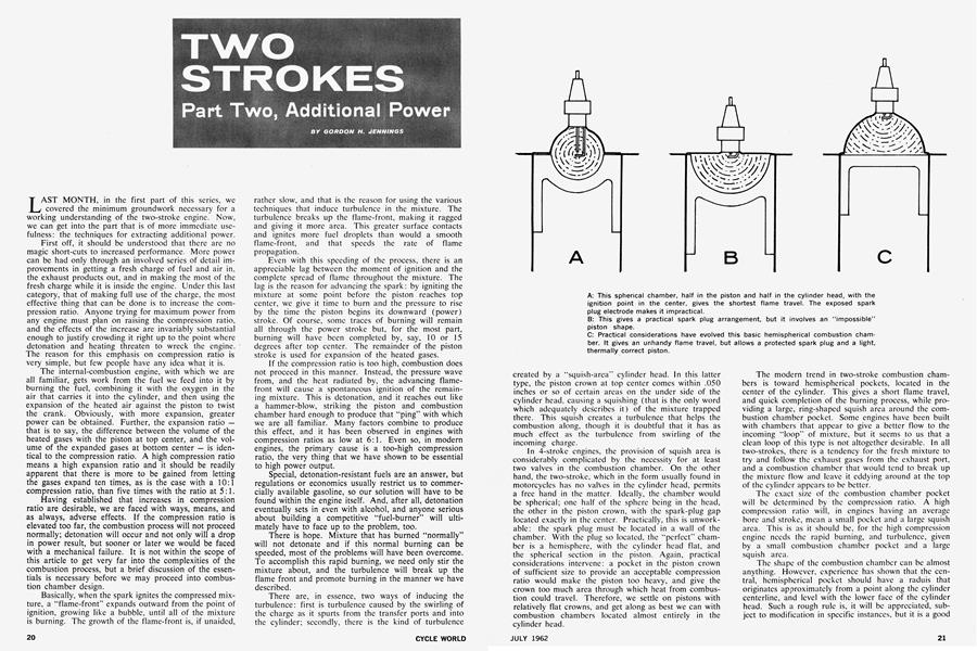
There are, in essence, two ways of inducing the turbulence: first is turbulence caused by the swirling of the charge as it spurts from the transfer ports and into the cylinder; secondly, there is the kind of turbulence created by a “squish-area” cylinder head. In this latter type, the piston crown at top center comes within .050 inches or so of certain areas on the under side of the cylinder head, causing a squishing (that is the only word which adequately describes it) of the mixture trapped there. This squish creates a turbulence that helps the combustion along, though it is doubtful that it has as much effect as the turbulence from swirling of the incoming charge.
In 4-stroke engines, the provision of squish area is considerably complicated by the necessity for at least two valves in the combustion chamber. On the other hand, the two-stroke, which in the form usually found in motorcycles has no valves in the cylinder head, permits a free hand in the matter. Ideally, the chamber would be spherical; one half of the sphere being in the head, the other in the piston crown, with the spark-plug gap located exactly in the center. Practically, this is unworkable: the spark plug must be located in a wall of the chamber. With the plug so located, the “perfect” chamber is a hemisphere, with the cylinder head flat, and the spherical section in the piston. Again, practical considerations intervene: a pocket in the piston crown of sufficient size to provide an acceptable compression ratio would make the piston too heavy, and give the crown too much area through which heat from combustion could travel. Therefore, we settle on pistons with relatively flat crowns, and get along as best we can with combustion chambers located almost entirely in the cylinder head.
The modern trend in two-stroke combustion chambers is toward hemispherical pockets, located in the center of the cylinder. This gives a short flame travel, and quick completion of the burning process, while providing a large, ring-shaped squish area around the combustion chamber pocket. Some engines have been built with chambers that appear to give a better flow to the incoming “loop” of mixture, but it seems to us that a clean loop of this type is not altogether desirable. In all two-strokes, there is a tendency for the fresh mixture to try and follow the exhaust gases from the exhaust port, and a combustion chamber that would tend to break up the mixture flow and leave it eddying around at the top of the cylinder appears to be better.
The exact size of the combustion chamber pocket will be determined by the compression ratio. A high compression ratio will, in engines having an average bore and stroke, mean a small pocket and a large squish area. This is as it should be, for the high compression engine needs the rapid burning, and turbulence, given by a small combustion chamber pocket and a large squish area.
The shape of the combustion chamber can be almost anything. However, experience has shown that the central, hemispherical pocket should have a raduis that originates approximately from a point along the cylinder centerline, and level with the lower face of the cylinder head. Such a rough rule is, it will be appreciated, subject to modification in specific instances, but it is a good place to start when re-designing the combustion chamber layout on an existing engine.
The squish area around the combustion chamber pocket must be handled with somewhat more precision. There is, after all, the squish effect to consider, and it will be less strong if a large clearance exists between the piston crown and the head with the piston at top center. For any appreciable results, the clearance should never be more than .100-inch and, to be really effective, it should be nearer .050-inch. Due to the irregular and uncertain “growth” of the engine components during running, the safe minimum clearance is approximately .040-inch. Anything less may result in the piston striking the cylinder head, with results that can only be harmful.
Entirely apart from the squish effect, there is another important reason for holding close clearances in the areas around the combustion chamber pocket. If the gap is too wide, the stagnant mixture trapped there — which is too confined to be swirling much — will have time, before being reached by the advancing flame-front, to heat up and detonate. If, conversely, the gap is small, the mixture will lose heat to the piston and cylinder head too rapidly for the critical temperature to be reached and detonation can be, to some extent, avoided.
Thus it is with combustion and combustion chambers in the two-stroke engine (and most of these principles apply, to a great degree, to four-stroke engines as well.) To get the highest compression ratio, the onset of detonation must be stalled by controlled combustion. Controlled combustion is, in the end, quick combustion, and to get that we need a generous squish area and a compact combustion pocket. Further, the pocket that is the best, thermally and in most other respects, is a spherical segment. Old engines may be given a huge shot in the arm by having their combustion chambers partially filled by welding, and then re-machined to give a higher compression ratio, and a good-sized squish area. The more ambitious may actually want to cast a special head, and that will give even more latitude in design.
In the selection of compression ratios for specific engines, only experimentation gives any real answers. Experience, that final authority, indicates that in smallbore engines, the compression ratio may be as high as 14:1. Bigger cylinders mean an increased tendency toward detonation, owing to the increased combustion difficulties in large burning areas, and a 250 cannot be expected to run at the same compression ratio as a 125. Of course, if the 250 is a twin, with cylinders having unit displacements of 125 cubic centimeters, the situation is radically different. We are of the opinion that unit cylinders larger than 125 cubic centimeters offer only limited hope in terms of pure power. However, should you be attracted by the torque of a “big” 250 single, an elliptical combustion chamber with two spark plugs, and a good, big squish area, might just be the answer to getting the compression ratio up high.
In discussing compression ratios, as related to the two-stroke particularly, the picture is complicated by the fact that compression does not truly begin until the piston has covered the cylinder ports. This is also true, but to a much reduced extent, of the effects of valve overlap on the actual compression ratio of four-strokes, but we must take that matter up another time.
Not having specific data on a large group of twostroke engines, we can only guess at the average discrepancy between the nominal compression ratio and the “real” one. We would guess the average “true” compression ratio for touring bikes to be about 70to 75percent of the nominal ratio. On racing two-strokes, which will have ports that extend somewhat farther up the cylinder, the true ratio may be no more than 65to 70-percent of the nominal. Thus, an engine for which a 14:1 ratio is given will, in fact, be operating at a true ratio of, perhaps, 9.5:1. In our estimation, this must be very near the practical limit for two-stroke compression ratios — running on pump gasoline.
Another of the factors limiting compression ratio is one that we have not mentioned until now: high compression ratios entail high thermal loadings, and the twostrokes — especially those with air-cooling — are not at all well situated to withstand heat problems. There is, as we have mentioned, only the most brief period of “rest” between power strokes, and with the crankcase in use as a scavenging pump, there can be no splashing of oil from the sump (such as can be provided in a fourstroke engine) to cool the underside of the piston. In any case, a problem exists, and increased compression ratios tend to be an aggravation. Compression of the mixture tends to squeeze out heat, and as this heat has no place to go but into the cylinder walls, head, and piston crown, the engine’s operating temperature is increased. The magnitude of this particular problem should not be underestimated; it is probably the most significant factor limiting the compression ratio of a two-stroke.
No one has, as yet, devised a means of entirely overcoming this basic limitation, but there are things that can be done that will help. Not surprisingly, all of these things are in the areas of better cooling, or more simply, materials that will withstand the higher temperatures involved. Of the former, we might as well state flatly at the onset that there are sharp limits as to what can be accomplished with air-cooling. Water-cooling of motorcycle engines is not popular, nor is it often attempted, but the objections are based primarily on economics, not engine efficiency. Radiators are inherently expensive, and one of enough quality and neatness of appearance to be left dangling out in the open, as would be the case on a motorcycle, would be doubly so. That, and the maintenance-free features of air-cooling, account for the lack of acceptance. In racing, these objections are not valid. The radiator need not be lovely; it only has to do the job.
Converting an air-cooled two-stroke to water-cooling is not really much of a job. Usually, an engine with iron cylinders will be the item for conversion and we have only to trim away the cooling fins and braze a lightgauge metal jacket. Separate jackets will, of course, have to be made for both cylinder and head, and some form of passage between the two, but the job is not impossible. To be most effective, the jackets should extend down around the area of the ports as much as possible. The extra, and uneven, sections of metal down there tend to make the cylinder distort locally and at that point the engine needs all of the help it can get.
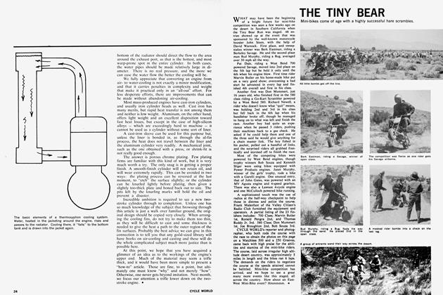
A water pump will not be required. Motorcycles have a considerable height, and a fairly tall, narrow radiator will give a thermosyphon action and provide adequate circulation. Remember here, that the factor is height. Hot water rises, cold water sinks, and by leading the heated water out the top of the engine, into the top of the radiator, and then out the bottom of the radiator and back into the bottom of the engine, the water inside the radiator will actually “fall” as it cools and establish circulation. The system must, naturally, be full to a point above the feed pipes before it will function.
The location of the feed pipes on the engine is quite important, too. Obviously, the best place for the water outlet is right in the center of the cylinder head, but the spark plug occupies that spot, so the outlet will have to be shoved over a bit. The cool-water inlet from the bottom of the radiator should direct the flow to the area around the exhaust port, as that is the hottest, and most warp-prone spot in the entire cylinder. In both cases, the water pipes should be made relatively large in diameter. There is no real pressure, and the more we can ease the water flow the better the cooling will be.
We fully appreciate that converting an engine from airto water-cooling is not exactly a minor modification, and that it carries penalties in complexity and weight that make it practical only in an “all-out” effort. For less desperate efforts, there are improvements that can be made without abandoning air-cooling.
Most mass-produced engines have cast-iron cylinders, and usually iron cylinder heads as well. Cast iron has many merits, but rapid heat transfer is not among them and neither is low weight. Aluminum, on the other hand, offers light weight and an excellent disposition toward fast heat losses, but except in the case of high-silicon alloys — which are exceedingly hard to machine — it cannot be used as a cylinder without some sort of liner.
A cast-iron sleeve can be used for this purpose but, unless the liner is bonded in, as through the al-fin process, the heat does not travel between the liner and the aluminum cylinder very readily. A mechanical joint, such as the one obtained with a press, or shrink-fit is not really good enough.
The answer is porous chrome plating. Few plating firms are familiar with this kind of work, but it is very much worth a try. The only snag is in getting a proper finish. A smooth-finish cylinder will not retain oil, and will wear extremely rapidly. This can be avoided in two ways: the plating process can be reversed at the last
moment, to “etch” the surface slightly; or the cylinder can be knurled lightly before plating, then given a slightly too-thick plate and honed back out to size. The pits left by the knurling marks will hold the oil and prevent a disaster.
Incredible ambition is required to see a new twostroke cylinder through to completion. Unless one has so much knowledge of the subject that browsing through this article is just a walk over familiar ground, the original design should be copied very closely. When arranging the cooling fins, do not try to make them too thin, as they will be difficult to cast and some thickness is needed to give the heat a path to the outer region of the fin surfaces. Probably the best advice we can give in this connection is to tell you that any good-sized library will have books on air-cooling and casting and these will do the whole complicated subject much more justice than is possible here.
At this point, we hope that you have acquired a glimmer of an idea as to the workings of the engine’s upper end. Much of the material may seem a trifle thick, and it would have been more simple to present a “how-to” article. Those are fine, to a point, but ultimately one must know “why” and not merely “how”. Otherwise, one never gets beyond imitation. Next month, we focus our attention a trifle lower down on the twostroke engine.