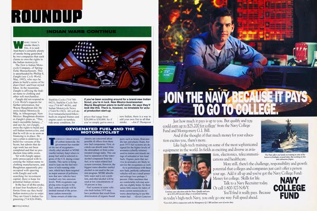
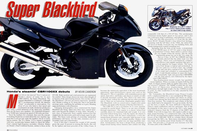
Computers Vs. Intuition
Computers vs. intuition
TDC
Kevin Cameron
I WANTED A CUP OF COFFEE TO WARM me on my November walk, but there was no coffee. In hat, coat and gloves, I let myself out of the borrowed cottage and set off down the lane. This was the especially penetrating cold of high humidity, sending icicle fingers down exposed necks and up sleeves. Soon, I came to the little lake, set in a deep natural bowl and surrounded with pines growing in sandy soil. This lake was steaming furiously in the new morning sunshine.
I climbed down to the shore and was fascinated to see long, graceful streamers of flowing water vapor, moving from the very edge of the water out toward the center. Behind me, a river of cold air was falling down the slope. Its weight was driving it silently through the trees, drawn to the lower pressure at the center of the lake where solar heat was lifting newly warmed air upward. Surface condensation was revealing all this motion to me.
I stood watching the noiseless traffic of many flows, colliding wisps merging and mixing in feathery grace as they glided away from me on the water’s surface. I was part of the picture, for when I moved, I shed tiny whirlwinds that waltzed away from me in stately fashion. A computer simulation of this would require billions of computations, but nature does its own figuring without silicon help.
Wouldn’t it be delightful to be able to see all fluid flow so clearly? That’s what Osborne Reynolds was thinking years ago when he injected a line of dyed fluid into clear glycerin flowing in a tube. Today, the “Reynolds number” defines the ratio of importance of viscosity and inertia in any given flow situation, and is used to establish dynamic similarity between model, laboratory flows and flows in the real world. To be an accurate simulation, a model test must reproduce not only the geometry, but also the Reynolds number, of the real flow.
As you’d expect, similar flows have been used to model engine airflow. In the real world, intake flow moves at hundreds of feet per second, sometimes just below the sonic boundary. Exhaust flow is sonic or supersonic much of the time. Either way, visualizing or mapping such a flow is difficult because of the high speed involved.
Well then, why not use water (800 times the density of air), but flowing at a much lower speed, to achieve an equal Reynolds number? We can mark the flow with dye, or with hydrogen bubbles generated by electrolysis, or in a variety of other ways. The equal Reynolds numbers allow us to be sure that the lower-speed model flow will be dynamically similar to the real flow.
To achieve rapid combustion, engineers need to know exactly how incylinder airflows are converted into useful turbulence, but flow-visualization methods such as smoke or dye are usefully visible only in laminar flow, for turbulence destroys the trace. A crude idea of flow can be had by dabbing carbon black in kerosene onto interior engine surfaces, then letting flow streak it. Flow probes can be inserted for measurements, but in turbulent flows this gives only highly averaged information. High-speed motion pictures can be made of fine particles swept along in the flow, then tediously analyzed.
Two more sophisticated methods are in wide use for engine-flow study today, and they approach the problem from opposite sides. One is Laser Doppler Anemometry, casually termed LDA by its users. Tiny particles are added to the airflow, which is illuminated at specific points of interest by crossed laser beams. The laser light reflected from particles moving through such a point experiences a phase shift because the particles are
moving. This is analogous to the rise and fall in the sound of a vehicle that approaches, passes and moves away from the listener-the Doppler effect.
Electronic processing allows the exact velocity and direction of the particles to be measured. By moving the beams’ crossing point through an engine cylinder, the entire flow can be accurately mapped at real-time speed. The measurement can also be pulsed to occur at a certain point in repeated cycling of the engine, so enabling a picture of the flow to be taken at specific points in the intake, exhaust or combustion cycles.
The opposite methodology is to predict what the flow ought to be from physical principles, using a fast computer running hydrodynamics software designed for the purpose. One such software family is KIVA, which was originally developed to numerically simulate what goes on inside a reacting nuclear bomb. Any such math model must necessarily make simplifying assumptions about reality just to make the problem manageable in the first place, so the accuracy of such modeling depends on the assumptions.
Nevertheless, it is likely that as computing power becomes ever-cheaper, more routine use will be made of such software in determining the best flow geometries for future engines. Wide use is certainly made today of specialized, over-the-counter software for boat and aircraft flow modeling, and engine-design software is widely offered. While such a software package may cost many thousands of dollars, that is surely cheaper than wind-tunnel or towing-tank time, and far cheaper than certain imaginable design mistakes.
Does this mean cut-and-try engineering is finished, and big money triumphs over experience? No, it’s far more likely that practical engineers will add computers to their toolboxes than that programmers will add internal-combustion common sense to theirs. Even the Japanese giants-all adequately stocked with computersstill employ cut-and-try methods on their highest technology, GP racing. That reliable, real-time, full-scale simulation that we call reality still has a place in engineering-especially in congenial combination with other useful things like die-grinders and intuition.