Suspension
SUSPENSION
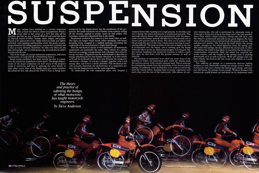
The theory and practice of softening the bumps, or what motocross has taught motorcycle engineers.
Steve Anderson
Magic carpets have nothing on a current motocross bike, at least not when it comes to suspension. Pluck a street rider or the owner of a 1972 dirt bike off his machine, put him on, say, a Suzuki RM250 and send him down an obstacle course of holes, bumps, rocks, ledges, and gullies. Watch as he approaches every ripple with eyes wide, jaw tightly clenched, veins popping and knuckles white. His panic circuits, programmed by his riding experience, scream that a painful end is near at every obstacle. Somehow, he rides over them all, the bike still upright, our terrified guinea pig amazed that he didn’t feel the jolts he saw.
This is the magic of current motocross suspensions, and every motorcyclist, on road and off, is benefiting from it.
Road racing machinery has been among the first to experience the motocross suspension trickle down. The design departments of the major companies are well aware of the progress made in motocross and they're applying the same lessons to their other racers. One of the Honda road race team members described his first ride aboard the FWS V-Four as being fasci-
nating not for the engine power, but the compliance of the suspension. He could accelerate out of bumpy turns without rolling off the throttle; applied to earlier racers he had ridden, this technique would have deposited him in the infield.
Suspension evolution has come to a few street bikes as well. The signs are longer wheel travel, softer springing, and better damping, often wrapped in a faddish package screaming the trademark of the manufacturer’s single shock design.
Past the mechanical clutter to first principals, all motorcycle suspensions are essentially the same. They consist of a spring that acts as a energy storage device, and a clamper that converts energy into heat. ( Engineers use the word damper to describe an energy absorbing device that damps vibration, so in this article we’ll call the hydraulic device that runs between the swing arm and frame a damper. If you put a damper together with a coil spring, then you'd have a shock absorber.)The mechanical details certainly determine the performance of a suspension system, but the fundamentals are the same regardless.
To understand the role suspension plays, first imagine a suspensionless bike running over rough ground. As the bike rolls over a bump, the entire motorcycle is accelerated upwards. This upwards velocity doesn’t die away immediately after the motorcycle crests the bump; instead, the bike leaves the ground, not to return until gravity pulls it down. The tires are in contact with the ground only part of the time, which makes steering or accelerating difficult. The load on either of the tires is high as the tire is accelerated over the bump, and is nothing past the bump when the bike is in the air. Horizontal progress was the goal, but the surface roughness has forced the machine to follow a path that goes up and down with the ground contour as well as forward.
The purpose of suspension is to allow the main mass of the machine to follow the horizontal path, while the wheels track the surface contour with a nearly constant load. This is achieved by isolating the w heels from the main body of the motorcycle by springs. In addition, some method has to be used to control the path the wheels follow, keeping them in proper alignment with each other and the rest of the motorcycle. (On almost all cur-
rent motorcycles, this job is performed by telescopic forks in front and a swing arm in back, but these aren't the only possibilities.) Now when a wheel contacts a bump and rolls up it, only the wheel is accelerated upwards to any great degree; the main mass of the motorcycle is isolated from the ground contour. The isolation isn't perfect. The load on the main frame, the sprung weight, changes by the wheel defection times the spring rate. The softer the springs, the less affected the motorcycle or rider. In addition the wheel is less likely to overshoot the bump than a suspensionless motorcycle. Only the wheel has acquired upwards velocity, and the weight of the sprung mass is pushing downwards on it as well as gravity. With soft springs and very light wheels, the load on the tire varies only slightly as it rolls over a bump.
The addition of springs to a motorcycle dictates adding dampers as well. Remember springs are energy storers. When a motorcycle runs over a bump, the springs gain energy, and once past the bump, the springs return energy. Without dampers the motorcycle would bounce up and down on its suspension until friction and internal damping in the tire rubber dissipate the energy. The suspension would be out of control during this period, so it’s easy to see why a more controlled damping mechanism is desired. For most of recent motorcycle history, this has been provided by hydraulic damping on the rebound stroke.
Another, less obvious, reason for damping was largely ignored until recently. A motorcycle runs over an incredible range of bumps, from smooth rollers to square-edged wheel destroyers, and it can run over these bumps over a wide range of speeds. None of this would make much difference if the wheels on a motorcycle were weightless, but alas, that’s not the case. This variety of bumps and speeds means that the wheels are forced upwards at a variety of speeds. If wheel speed is great enough, the wheel will overcome the spring and continue upwards past the bump just as a valve floats off a camshaft when engine speed is too great. The spring doesn't care how fast the wheel is moving; it exerts a force that is dependent only on how far it is compressed. What motocross has shown is that it's not appropriate to resist wheel movement strictly as a function of position. The wheels can be kept in better contact with the ground with velocity sensitive compression damping adding to the spring force. The damper resists wheel movement with a force roughly proportional to wheel speed; the faster the wheel is pushed upwards, the more the damper pushes back.
SUSPENSION REQUIREMENTS
Springs and dampers are the basic tools of suspension design. Which spring and damping rates are used depends on how a motorcycle is used. There are, however, some generalizations. Soft springs are better than stiff springs. They feed smaller forces into the motorcycle, reduce peak tire loads and keep the tires on the ground the best.
Soft springs require more suspension travel to carry the same load. That's another generalization. If suspension travel increases 10 percent, the spring rate can decrease 10 percent.
The load on a suspension results from two very different factors. One is the weight of a motorcycle; this must be handled when the bike is braking, accelerating or cornering. The other load comes not from the bike, but from the ground. These are the bumps and jumps that impose shock loads on the suspension.
Loads from motorcycle weight are more sustained, and more predictable. People who set up suspensions have their own rules of thumb about spring rates and preload. For example, Gil Vallaincourt of Works Performance figures that the rear suspension of a motocrosser should require 130 percent of the bike and rider weight to be fully compressed. A road racer or street bike should only require 1 10 percent of the bike and rider weight for full compression, he says. The motocrosser receives greater shock loads from the irregular terrain, so the suspension needs to absorb those greater loads without bottoming.
Even if long-travel suspension requires the same force to be fully compressed, it is less likely to bottom when landing from a jump or hitting a sharp object. The ability of a spring to absorb energy affects this. Energy absorption increases proportionately with spring stiffness, but increases squared with deflection. This allows long, soft springs to absorb more energy than shorter, stiller springs that compress fully under the same load.
Damping also benefits from longer travel suspension. With a greater distance to absorb energy, the damping rate can be lower, making for a more compliant suspension. The damping that works best is, generally, speed sensitive. The force that resists wheel movement is directly proportional to wheel speed.
Damping rates are normally different on the compression and rebound strokes. On automotive shocks, numbers like 3070 and 50-50 have been used, indicating that, for example, 30 percent of the damping force is on compression and 70 percent is on rebound. Motorcycle suspensions aren't that simple. Damping is used for entirely different purposes in the two directions. Rebound damping is determined by spring rate, the weight of the rear tire and wheel and the damping forces. On a fall-away jump, the fastest rebound speeds are reached, and this might be 6 to 10 ft./sec. But hit a squareedged bump with the same bike and the wheel speeds can be over 30 ft./sec. This compression speed is also determined by the bike's speed. Hit a bump faster, and the wheel moves faster. Rebound loads aren't affected this way.
Figure 1 shows damping force versus wheel speed for two applications. Notice that there’s no such thing as a damping curve that’s perfect for every type of use. Motocrossers run over large bumps at relatively low speeds, and the wheels are able to respond quickly enough to follow the ground contour. In addition, they have to deal with high energy landings from jumps. Because of these factors, motocrossers respond well to the almost linear damping curves shown in Fig. 1. A higher speed application like road racing requires different curve shapes. Speed has increased, and the typical bumps are smaller and more abrupt. The wheels simply can't move quickly enough to follow every surface roughness. Instead, damping curves are often used that have linear damping at low wheel speeds, and flatten out at higher speeds. The low speed damping is there to damp out the pitch and bounce oscillations of the sprung mass, particularly where the motorcycle rocks back and forth on its suspension. That oscillation makes the motorcycle likely to w'eave and feel unstable.
Note that while the shape of the curves shown in Fig. 1 may be typical, the magnitude of the damping forces required for different machines will depend on wheel travel, overall vehicle weight, wheel weight, and spring rates. Damping curves for successful suspensions are almost always determined by testing with actual motorcycles in real world conditions, and not just by analysis.
One aspect of suspension can be stated unequivocally for any motorcycle application; the lighter the unsprung weight (the wheels, tires, brakes, and suspension components), the better the suspension
will work. Heavy wheels have their own upwards inertia cresting a bump, and are more likely to overshoot the top of it than a lighter wheel. On the rebound stroke, the heavy wheel can’t extend as quickly. Less unsprung weight allows the-tires to track the ground contour better, and spend less time in the air.
What determines suspension travel for different types of motorcycles? If softer suspension is better, why don’t they all have 12 in. of travel? Suspension travel is a trade-off with other aspects of motorcycle handling, and the trade-off is dependent on the surface the bike is operating on. Longer suspension means a taller motorcycle with a higher center of gravity, a motorcycle that’s more likely to do wheelstands on either the front or back wheel. In addition softer suspension means the motorcycle will pitch more during turning, braking, or accelerating, perhaps leading to handling problems or loss of steering precision. Beyond these dynamic effects, longer travel means a higher seat height. Softer suspension means the ride height is more sensitive to load changes, which can lead to problems on street motorcycles which have to work with either 130 lb. of rider or 400 lb. of rider, passenger, and baggage. Use determines travel for different motorcycles. Motocrossers, required to travel over the worst terrain, now have 12 to 13 in. of wheel movement at both ends. Road racers, which operate on relatively smooth tracks but are searching out that last bit of tire traction, currently are using 5 to 6 in. of travel and softer springing than most street bikes of the same weight. Street bikes are in a period of evolution, with the travel increasing from the traditional 3 to 4 in. to something more like the road racing norm, with springs softening with the longer travel.
A final task for suspension, whatever the amount of travel, is to provide a smooth transition from normal operation to the extremes of wheel travel. All motorcycles are likely to encounter conditions that will cause the suspension to bottom or top out, hitting the travel limiters on either end of suspension movement. If the wheel is stopped with a clang at the limits of travel, both rider comfort and wheel control are reduced. To avoid this, springing or damping should stiffen at the ends of travel. This is more important for bottoming than topping, for the same reason the compression stroke is different from the rebound.
THE HARDWARE
The requirements listed above would be met by ideal suspension components; how close does motorcycle hardware come to that ideal?
The brief answer is, much closer than it did a few years ago. To understand
how the hardware matches up to suspension demands requires a closer look at individual components.
While theoreticians may divide suspension into separate springing and damping functions, in reality they’re almost always combined into a single mechanical unit, be it a shock absorber or fork leg. The most common spring is steel coil. A spring of any type is generally categorized by its spring rate, or that amount of force required to compress it a specified distance. The simplest coil springs have a constant spring rate: up to the point the spring is coil bound, a 100 lb./in. spring will be deflected an inch by a 100 lb. weight, regardless of how far the spring has already been deflected.
A coil spring stores energy by twisting, not bending, the wire in its coils as it compresses. As the wire diameter drops, it becomes easier to twist, so a spring made from smaller wire has a lower
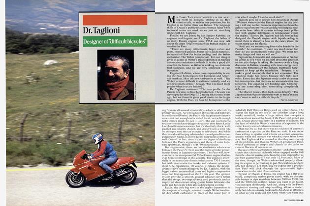
The twin tube damper was the standard for early motocross, but the rigors of this application emphasized its problems.
spring rate than a spring made from thicker wire. The spring rate also drops with increased wire length (more coils) and with larger coil diameter. Larger coil diameter gives more wire length per coil, and also gives the force acting on the spring more leverage to twist the spring wire. This is why the current single shock machines have to use such large diameter wire to compensate for their large diameter springs.
There’s an important distinction between the rate of the actual spring, and the effective rate at the wheel. The rate at the wheel is known as the wheel rate, and is the amount of force required to move the wheel a certain distance. If the wheel and the spring move the same amount, as at the front forks, the wheel rate and combined spring rate are identical. At the rear wheel, however, the spring only moves a fraction of the distance the wheel moves. The relationship between wheel movement and spring movement is called the leverage ratio. Rear suspension leverage ratios have a compound effect. Consider, for example, a swing arm with a 100 lb./in. spring mounted halfway between the pivot and the rear wheel. That would provide a 2:1 leverage ratio. Move the rear wheel up
one inch and the spring is compressed a half inch. That requires 50 lb. of force at the spring, but the 2:1 leverage ratio means that only 25 lb. of force is needed at the rear wheel. This ratio applies to both the force and the distance, which makes the spring rate the square of the wheel rate.
The wheel rate is valuable in comparing springing from one motorcycle to another. Leverage ratios vary tremendously, and there are some extreme cases of single shock motocrossers where an 800 lb./in. spring is used with such a high leverage ratio that the wheel rate is 30 lb./in. The 30 lb./in. would be the rate the rider would feel in this case, and could be used for comparison with other similar motorcycles regardless of what combination of springs and leverage was used to obtain their wheel rate.
Remember that one of the requirements for suspensions is to increase the spring rate near the end of travel. One way to do this is with progressive rate coil springs. These can be made by varying the pitch spacing of the coils, or by making the coils from expensive taper ground wire. These techniques are costly, and have some limitations on the spring rate curves that can be obtained. A more common practice on current designs is to use two or three single rate springs stacked in series along with spacers that control the amount each spring can deflect. When two springs are stacked in series, the combined spring rate is less than either of the springs by themselves. The spring rate of the spring stack is this lower combined rate until the spacer limits the travel of one of the springs; then the spring rate increases to that of the spring that can still move. Since the spacer controls the point where the spring rate crosses over from one rate to the other, it’s commonly known as a cross-over spacer.
An alternative to steel springs occasionally seen on rear suspensions and always affecting the front forks is the air spring. Energy can be stored by compressing air just as it can be by twisting steel in a coil spring; the difference is in the resulting spring rate curve. An air spring obeys Boyle’s law: the change in air pressure is inversely proportional to the change in volume. If the volume inside a spring is reduced to half, the pressure doubles. This behavior is used to give truly progressive springing.
All conventional forks, even without air caps, act this way. A volume of air is trapped inside the forks, and when the forks are compressed, the air pressure increases, reaching a peak of about 100 psi. The total spring rate can be easily changed by adding or bleeding air pressure through air caps, or the volume of air can be changed by adding or removing fork oil. Less oil leaves more volume for air, more oil makes less air volume. The difference in volume from extended to compressed varies more when the oil level is high and the air volume is low, making for more progressive springing.
Air makes an easily adjustable, lightweight, progressive spring, but there are drawbacks. First, the chance of a leak is greater than the chance of breaking a metal spring. Second, the air chamber has a sliding joint that has to be sealed. Lip-type seals (the type used as fork seals) generate increased friction as the pressure they’re required to seal increases. Consequently high pressure air systems are troubled by friction, a real departure from ideal suspension practice. Third, single chamber air systems have difficulty giving the desired spring rate curve. If an air system is designed to start with the same initial preload as a conventional single rate spring, it has to be very progressive to reach the same load at full compression. This progressiveness means that the initial spring rate is low, and the bike sits much further into its suspension travel statically. Or, if the spring is designed to give the same ride height as the coil spring alternative, it has to have less volume change and progression, and start with a much higher preload. This makes the suspension more likely to top out. One solution is a two chamber air system, an approach used on early 1970’s Yamaha motocross forks and then with the Fox Air Shox. By the time a second chamber has been added, much of the initial simplicity that made an air spring attractive is gone. The final problem with air is that pressure varies not just with volume, but also with temperature. Air pressure rises when temperatures rise. When an air chamber is wrapped around a hydraulic damper that’s busily turning mechanical energy to heat, the one thing that can be guaranteed is a rise in air temperature. The spring rate and preload won’t be a constant, but will depend on exactly how hot the damper has become. Because of these problems, air is being used mainly as a supplement to coil springs, adding progression and adjustability to an essentially metal spring system.
The final spring medium commonly used on motorcycles isn’t obvious—rubber. Rubber bump stops are combination springs and dampers. The best ones are made from urethane foam. Their spring and damping rates are controlled by a combination of the particular rubber properties and the exact shape of the bump stop.
While springing is handled by different techniques, damping is currently accomplished in one basic way, pumping oil through a restriction. Generally, a piston moving with the wheel is pushing oil from one chamber to another. The chambers are separated by a small orifice. The oil passing through the orifice has to accelerate, gaining kinetic energy as it gains speed. Once through the orifice, the oil’s speed and energy are dissipated in heat-generating turbulence.
Hydraulic damping hasn’t always been used in suspensions. Before reliable oil seals existed, cars and motorcycles used rubbing friction for suspension damping, but this practice was discontinued as soon as reliable hydraulic dampers could be made because the damping curve was wrong with friction dampers. The force exerted by friction isn’t strongly affected by speed; it resists the smallest bump the same as the biggest. Hydraulic damping has a fundamentally different characteristic. In the simplest case, where the orifice is a constant size, the resistance to movement increases at the square of the shaft speed. That damping curve isn’t much better than the one that friction provided, but there is an important difference. Hydraulic dampers can be designed with valving systems that give a variable orifice size. As speed and pressure increase, so does the orifice area. This technique allows hydraulic dampers to have almost any damping force vs. speed curve desired. It’s worth noting that hydraulic dampers haven’t eliminated friction damping from the suspension; now friction damping remains as an undesirable result of friction in pivots, the hydraulic dampers themselves, and other rubbing surfaces in the systems. This friction detracts from suspension performance, and is being eliminated wherever possible.
The classic hydraulic damper is the twin tube design. The inner tube of the twin tube design is full of hydraulic oil, and a piston at the end of the damper shaft divides the inner tube into a upper and lower section. Because the incompressible hydraulic oil inside the inner tube can’t cope with the reduced internal volume when the shaft enters the inner tube, the outer tube is added to the damper. It contains hydraulic oil at the bottom, and air at the top. A damper filled with oil couldn’t be compressed, so the air is used. It compensates for the volume of the shaft when the damper is compressed.
Rebound damping in the twin tube damper is controlled by valving in the piston. As the wheel extends, oil is trapped between the top of the piston and the oil seal at the top of the inner tube, and is forced to flow through the rebound orifices in the piston. Compression damping has to be controlled by a different mechanism. Imagine what would happen if valves in the piston attempted to control compression damping. The piston would descend, but the oil below it wouldn’t be trapped because it could flow into the outer tube, compressing the air there. There would be only a slight pressure build up to force oil through the piston valving, and the pressure in the upper chamber would drop, falling below atmospheric pressure. Cavitation, the vaporization of oil from low pressure, would occur in the upper chamber. Not only does this scheme not work for compression damping, it would ruin rebound damping on the next stroke because of the incompletely filled chamber above the piston. Accordingly, on twin tube dampers compression damping is controlled by valving between the inner and outer tubes instead of piston valves. Only the small amount of oil displaced by the shaft entering the inner tube is metered into the outer tube on the compression stroke, and large one-way valves in the piston replenish the oil supply above the piston.
The twin tube damper was the standard for early motocross, but the rigors of this application emphasized its design problems. A damper turns mechanical energy into heat, and the outer tube served as an effective insulator, trapping the heat inside the damper. The small amount of oil metered on the compression stroke made precise control of compression damping difficult. The worst problem was that the air and oil in the damper didn’t stay separate, but formed an emulsion with properties very different from hydraulic fluid. The emulsion was compressible and passed through the valving more easily than pure oil. The rider felt this change as fade; the damping decreased and the bike bounced around.
Designers responded to these problems with two different fixes. The first was to continue with the twin tube design, but isolate the gas inside a plastic bag in the outer tube. The second was to stop worrying about the mixing and design a single tube damper with valving designed to operate on an air-oil emulsion. Both designs were improvements, neither was the final answer. The twin-
tube with isolated gas still had problems with heat build-up and precise compression damping. The single tube emulsion damper was easier to cool without the outer tube for insulation and could meter both compression and rebound damping with valves in the piston. Unfortunately the compressible air-oil mix didn’t allow damping as consistent as that provided by pure oil.
The deficiencies of these two damper designs led to the adoption of the gas pressurized damper (known as the DeCarbon damper after the man who invented and patented it.) The DeCarbon damper separates the oil from the gas with a movable piston or flexible bladder, and the gas is pressurized to 200 to 400 psi. The separation ends gas and oil mixing problems, and the high internal
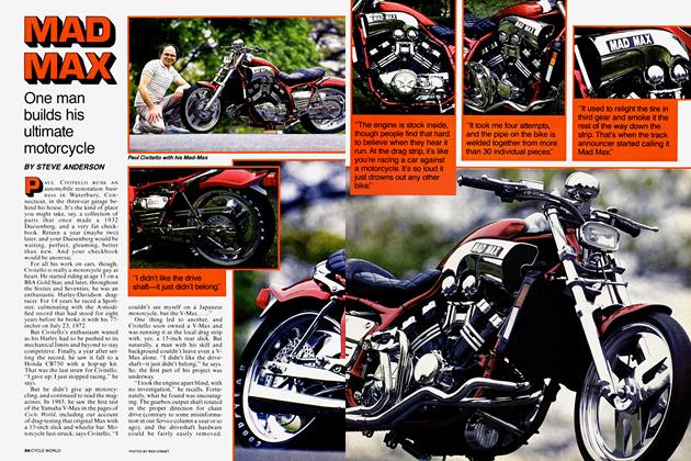
Front suspension will match the rear in sophistication, first in racing applications, filtering down later to street bikes.
pressure eliminates cavitation concerns. Both compression and rebound damping are metered by valving in the piston. During normal operation, the oil pressure on either side of the piston is equal to the gas pressure. As the piston descends on the compression stroke, the oil pressure on top of the piston drops, and the pressure on the bottom remains at the gas pressure. So a DeCarbon damper can exert a compression damping force equal to the gas pressure times the piston area before the oil pressure above the piston falls below atmospheric pressure.
Once it was being used in motocross, refinements were made quickly to the basic DeCarbon design. There were two goals for these changes: more consistent damping and less friction. The gas chamber was moved out of the damper body to its own compartment. This gave more shaft travel for a given damper length, a larger gas and oil capacity, and kept the gas temperature, and therefore the gas pressure, more constant. The seals and bushings inside the damper were upgraded to slippery, low-friction designs. The valving in the piston was designed to be sensitive to the volume of oil flow, and not the oil viscosity or thickness.
This was an important improvement. The operating temperature of the oil in the damper could vary by as much as 200° between cold and hot, and the oil
viscosity could easily vary by more than a factor of 10 over this temperature range. (Recall how slowly oil pours out of a can, and how quickly it runs from ? hot engine during an oil change.) If valving is sensitive to viscosity, the damper fades when it gets hot. With the improved valve system, damping could no longer be changed by changing oil weight; instead the designers incorporated methods of changing the damping by changing valve components.
These changes bring us to the present state of damper design. The leading companies are manufacturing the highest quality dampers that the motorcycle or automotive industries have ever seen. Refinements, such as external damping adjustments and friction reductions continue, but essentially damper design is a mature technology. Advances will not come as rapidly in the future as they have in the last few years.
While rear suspension dampers may not have much room for improvement, the same cannot be said for the dampers in the front forks. Without any barrier to separate the air and oil, they operate as emulsion dampers. Besides that, most forks use a fixed orifice design that has been obsolete for the rear suspension for more than 20 years. The rear wheel is the driving wheel on motorcycles, and improvements to the rear suspension have offered the quickest lap time payoff. Now that rear suspension is worki well, more attention is being paid to : front. The Simons upside-down fc that Brad Lackey used to win the 50 GP world championship had variaarea valving much like that used for real dampers, and so do the Showa forks used on the 1983 works Honda motocrossers. This is the trend that will surely continue: the front suspension will match the rear in sophistication, first in racing applications, filtering down later to street bikes.
As wheel travel approached the limits of usability in motocross, and as dampers became a consistent part of the suspension rather than a problem remaining to be solved, chassis designers had to rethink the rear suspension before they could improve it further. The innovation they chose to explore was the progressive linkage single shock. This didn’t entail any fundamental changes in springs or dampers. Coil springs and DeCarbon dampers were scaled up to the appropriate size. The new addition was a combination of links and pivots that varied the amount the rear shock was compressed depending on where the rear wheel was in its travel. The leverage ratio changed substantially depending on the wheel position. The design of the linkages, despite their disparate appearances, shared a common source in a simple toggle linkage, the same type that gives variable leverage to Vise-Grip pliers. With Vise-Grips, your leverage on the part in the plier jaws improves the farther you squeeze; with the single shock linkages, the shock’s leverage on the wheel improves the further the shock ft compressed.
continued on page 95
Continued from page 54
The progressive linkage designs neatly met one of the requirements for a suspension system: that the spring and damping rates should increase toward the end of travel to cushion bottoming. The linkage system on some Suzukis and tlondas do this so successfully that it’s almost impossible to feel the suspension bottom, and the aftermarket shock manufacturers note that bump rubbers are much less important on single shock designs than they are on non-progressive dual shocks. But beyond acting as a complicated substitute for bump rubbers, the linkages are exploited for other reasons as well. They allow tailoring the spring pte curve to soften the rate near the normal ride height, and stiffen it several inches into the travel. The soft initial rate provides a better ride over small ripples, and the firmer rate later is a necessary evil.
It’s impossible for someone without access to proprietary test information to judge exactly how important progressive linkages are to current motocross suspensions. Relatively non-progressive (fual shock suspensions used on Husqvarnas work nearly as well as any of yie current single shock systems. Correct spring rate, damping rate and wheel travel may be responsible for the greatest part of a suspension’s performance, and the progressive linkage is the frosting on t<he cake. In the cases where bushings at the pivot points contribute excessive friction, linkages are almost certainly a performance liability. The better performing single shock linkages all use roller bearings at the pivots.
What 10 years of motocross suspension technology have given the motorcycle companies is just that—a suspension technology. The exact solutions that worked in motocross can’t be transferred directly to other types of motorcycles. What can be transferred is the basic technology—dampers that offer consistent performance, linkages that enable the spring and damping rates to be position sensitive, and test procedures that reflect real world conditions. In the case of road racers, this technology has taken them from the point where the suspension that worked best was the one that let the wheels move the least, to the current level where the suspension actually allows them to go around a bumpy race {¡rack faster. Expect similar progress on street motorcycles. gg