Frame Work
FRAME WORK
Eggshells, Spaghetti or Big Steel Tubes; Form and Function Mean More than Material.
Lane Campbell
Without a frame, a motorcycle is just a collection of parts. There have been motorcycles built sans frames, as such. Most notable were some of the Vincents, in which the steering head bolted to the oil tank, which bolted to the engine, which bolted to the rear suspen sion, whose springs reacted back into the oil tank. Those who have ridden the end result say they handle rather-erstrangely. Rather a shame it was to try to make that magnificent engine double as a frame. It just wasn't shaped right.
For in a frame, shape is critical. It’s really more critical than substance. Shape, form, geometry, whatever you choose to call it, makes more difference to a frame’s performance than (say) the difference between mild steel and chrome-moly. If form is critical and form follows function, we’d best zero in on a frame’s function.
Very crudely stated, a frame connects the front wheel to the rear wheel and keeps everything else from falling on the ground. OK, don’t shoot. There’s more to it than that, but that’s what it boils down to.
Actually, a frame has two main jobs to do, and their relative importance varies with the purpose of the particular motorcycle. First, it must maintain its structural integrity under stress. That means, when the motorcycle is ridden as intended, the frame mustn’t bend permanently or break. Note I said “ridden as intended,” for the character of stress varies with the end use of the bike. That character often determines the form and substance of the frame. More on that later.
Second, the frame must maintain critical alignments under stress. In other words, it must be rigid. It not only can’t bend permanently, it ought not to bend temporarily, either. Most production frames do bend. To illustrate, watch a production road racer in a bumpy corner. Viewed head on, you can see its front tire twisted out of plane with its rear tire; which means the wheels aren’t running on a common track. If the wheels aren’t running on a common track, the motorcycle is steering, whether the rider wants it to or not. This is likely to upset him greatly. Sorry ’bout the pun.
OK, I’ve belabored the most obvious critical alignment, that of the front and rear wheel. It may be more critical for a 180-mph road racer than for a moped, but it’s only a matter of degree. It may be more critical for a street/touring machine than for a dirt bike, if only because a dirt bike is subjected to so many off-center shock loads that the disturbances caused by frame flex can get lost in the shuffle. However, if frame flex on a motocrosser should (say) cause the swing arm pivots to become misaligned and bind, that's critical.
Enough. Suffice it to say that the frame should be stiff so as to hold the parts in the relation which the designer intended for them. In these raw examples, we’ve already seen how design objectives and intended uses bear upon what’s critical.
Now it’s time to make some generalizations that apply to all frames. They can all be studied by thinking of them as a combination of beam and torsion bar. It’s also time for a definition or two.
Beam: A member supported at one or both ends, subjected to various loads along its length that would cause it to bend.
Torsion Bar: A member supported at one or both ends, subjected to various loads along its length that would cause it to twist.
Why go through all this? We have to get a handle on a frame’s dual personality, by learning how it reacts to various riding stresses. Start with the motorcycle just sitting or running straight up. In this mode, it’s a plain beam—simple model in Fig. 1 A and a more complex closer-to-real picture in Fig. IB—supported at two ends, loaded at various points by engine, rider, and major accessories, also loaded along its whole length by its own weight. If it hits a bump running straight up, it’s still a beam, unless the bump is shaped so as to knock one wheel sideways. (More on that later.) If it is in a stable cornering attitude, with no rider steering inputs, it is also a beam. (See Fig. 2.) What a straight-up bump or cornering loads do is magnify all the loads on it, sometimes by a factor of four or more.
OK, that’s one mode of frame loading— the beam mode. What if a bump kicks a wheel sideways? Or more commonly, what if the bike hits a bump while cranked over—first with the front, then with the rear wheel? In either case, the tendency is to twist the frame. If the rider suddenly throws a lot of weight into the bars to pick up or heel over, then there’s a sudden sideways force reacted through the front wheel contact patch; this, too, has a twisting effect on the frame.
If the frame responds to these twisting loads by actually flexing appreciably, it will cause the wheels to run on diverging paths, which will in turn cause the rider to say, “This thing acts like it’s got a hinge in the middle!” (Does it strike you as ironic that most motorcycles have two hinges in the middle? They’re called the swing arm pivot and the steering head. When the frame’s working properly, you’re not supposed to notice.)
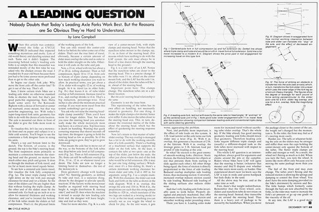
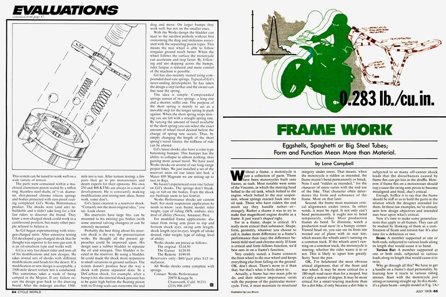
OK, what’s “appreciable” flex? To get a handle on that, we can look at a simple theoretical model. Our material will be steel, which weighs about 0.283 lb./cu. in. and has a “shear modulus” of 12,000,000 psi. That last number is a critical measure of a material’s ability to resist deformation when twisted. Note that I’ve not said “mild steel” or “chrome-moly” or any other qualifier. That’s because the shear modulus for all kinds of steel is virtually the same. That means that up to its elastic limit (the point at which it bends permanently) a piece of mild steel is just as stiff as a piece of chrome-moly. So what’s the big difference? Chrome-moly has a far higher elastic limit. Oh.
For our model, suppose we first take a 1-in. diameter solid steel bar 4 ft. long to represent a single straight frame member connecting steering head to swing arm pivot. We clamp one end to some rigid reference and hang a 3-ft. lever on the other end. (Fig. 3.) The lever represents the distance from steering head to tire contact patch, measured along the forks. If you laid your weight (say 200 lb.) on the end of the lever, the end would deflect about 10 in. A 4-ft. steel bar, which weighs about 10’/2 lb., is obviously a lousy frame.
Hm. Let’s try a 2-in. diameter tube with 0.1-in. wall thickness. Same lever arm, same load, we get about 1.6-in. deflection. Better, but no cigar, although the tube’s weight is only 8.5 lb.
Try 3-in. diameter tubing next, in 0.1-in. wall thickness and in 0.05-in, wall. The thick wall tube weighs 12.8 lb., and the thin wall version weighs 6.4, roughly. Deflec. tion is about 0.47 in. for the thick wall version and 0.94 in. for the thin wall. Going one step further, a 4-in. diametei tube with a .05-in, wall weighs 8.5 lb. (same as a 2-in. thick wall) but deflects about 0.4 in. at the lever end.
By now it's evident that as we bump the diameter and decrease the wall thickness of a tubular member, we improve its stiff ness/weight efficiency. The only limit to this kind of logic is buckling. Too thin a wall will crumple like a sheet of paper. You can make a very stiff, strong structure out of paper set on edge, or for that matter, eggshells as long as you stress it carefully.
Let the stress get a hair out of line, and the house of cards comes down; the eggshell cracks.
What we've been dealing with here is a thing called section modulus, a measure of how much material is concentrated how far from the cross-section centerline. For circular-section members (like rods and tubes) it's very easy to figure. Fortunately, it also turns out that circular sections are most efficient in resisting twist; other shapes tend to lose something. However, for any shape, a general rule applies: The section modulus (hence the inherent stiff ness) is greater with the greater amount of material concentrated further from the cross-section centerline.
So. A most efficient single-member frame would be a giant straight tube (a curved one is less stiff) with wall just thick enough to resist buckling, connecting the swing arm pivot with the steering head. (See Fig. 5.) There are still some limita tions. Like, where do you put the engine?
Granted, some mopeds and other tid diers actually do have straight-tube single member frames. Their engines are small enough to fit into that rough triangle be tween frame tube, wheel and ground. With anything bigger, you have sacrifices to make.
The celebrated monocoque (single shell) and pressed-steel T-bone frames are simply variations on this theme. They are made in more complex shapes than a simple straight tube in order to leave space: for the engine and to bend around other critical parts. Yes, they do lose something from the ideal, both in terms of stiffness! weight and in ease of fabrication. -
Because the engine sits where it does, and because it gets in the way of things theoretically perfect the way it does, multi tube frames have evolved. That may seem an over-simplification, but, by Gadfry, it's true. There are many ways to provide a rigid structure between two points. Bridge builders have been doing so for years, with a thing called.a truss.
No, it's not something you wear for a hernia. In engineer talk, a truss is any system of members that are stressed only in tension /compression. never bending or twisting. The members are related to each other in such a way that, even if they were joined by pins, they would not rotate about each other. The structure would remain ri -gid,upto the limit of the weakest member.
A triangle (1-ig. ô) is the building block of a truss. If you replaced all its points with hinges, the joints still couldn't be moved without breaking one of the sides. A square is not a truss. Put hinges on its corners and it flops. Put a diagonal across it and pin the joints; now it's a rigid truss made of two triangles. Aha, triangulation! Sound familiar?
One quick time out. We mentioned bridges. Bridges are beams. A two-dimen sional truss, then, is a fitting structure for a motorcycle frame loaded as a beam; and when analyzing motorcycle frames, people often get into this two-dimensional truss! beam frame of mind. (Ooops, did it again, didn't I?)
All well and good. but we're talking about twist/torsion. Since our problem is fighting torsion, our truss motorcycle frame must be triangulated in all three dimensions-a triangulated solid. See Fig. 7, which shows one of the simplest tri angulated solids-a tetrahedron, with a steering head at one end and a swing arm pivot at the other.
Right away you ask yourself, again, where's the engine going to go? (The one drawn superimposed is, of necessity, very narrow.) Where's the sub-~frame to support the rear suspension? The rider? Besides, this unbraced tetrahedron, while the oretically rigid, has such a narrow base at one end that the members are worked at a mechanical disadvantage. OK, so much for simple and/or theoretically perfect. The real-world multi-tube frame is a com promise over theory, dictated by where the engine and suspension have to go to make the motorcycle work-as a motorcycle. You just can't design structures in a vacuum.
Here's another consideration that shoots holes in our theoretical truss. In a real motorcycle frame, the joints aren't pinned. They're welded. Pinned joints are some thing you use in theoretical study because they, by definition, determine that no bending stresses can be reacted into the members of the truss.
Welded joints are (for all practical pur poses) rigid; and they do react bending stresses into the frame. Ergo, all the mem bers of a multi-tube frame actually wind up being subjected to tension/compres sion, bending, and sometimes to twisting, simultaneously. One way to stiffen such a multi-loaded structure is to reduce the unsupported length of the tubes, by plac ing cross-members between them, ladder style. To further gild the lily, one can triangulate each ladder-section with a di agonal. Carried to extremes, you wind up with a spaghetti-tube frame made up of lots of tiny tubes instead of one big one.
Realize that both the eggshell and the spaghetti are extremes; one the ultimate simplicity, the other the ultimate complex ity. Designers have moved in both direc tions~ Remember the Yetmän "space frames" of the early Sixties? The John Player works Norton, which was built and raced both ways, is a perfect example of design proceeding in both directions dur ing the lifespan of one project. The English have a flair for that sort of thing.
Ultimates and extremes have a way of getting shoved aside by efficient compro mises. We're talking curved tubes instead of straight ones. Gussets and cross-mem bers in lieu of perfect triangulation. Let's look at some of the shapes that work out in general practice.
Motorcycle frames (swing arm variety) generally fall into one of four basic shape! categories: closed loop, open ioop, can tilever (or semi-cantilever), and backbone.
Closed loop is the familiar dirt bike layout, in many variations based on num ber of top and bottom tubes. The most: common open loop is an open-bottom type in which the engine completes the bottom part of the circuit. Examples include the Ossa trials bike and the Yamaha TY250 trialer, both, ironically, owing their shape to the influence of one Mick Andrews.
Another, which really did use the engine cases as a stressed lower member, was the 250cc Parilia Gran Sport. This open-bottom frame depended so much on the engine that with the engine out, the bottom ends would actually spread out about lA in. as the chassis flexed under its residual weight. These babies weighed about 187 lb. soaking wet, however, and racked up quite a competition history in their short lifespan. Primo collector’s item today.
Cantilever frames are so named because, with no major structure in front of or below it, the engine is supported cantilever-fashion; i.e., supported at one end only. Semi-cantilever frames supplement this one-ended support with a minor subframe of some sort. Yamaha’s Sixties-vintage 100 and 125 Twins used a bolt-in tube to support the front of the engine. Honda Super Hawks (the originals) supported the top of the engine from a small hanger. In general, semi-cantilever members function mostly to keep the engine from falling out: They lend little or no stiffness to the overall structure.
Backbone frames sometimes look like cantilever frames, but differ in one important respect. They are generally curved to pass around (over) the engine, losing stiffness by the fact of that curvature. To gain it back, the engine, which is slung under the backbone, is mounted rigidly so as to form a closed loop between the ends of the curved tube structure. The Laverda 750SF Twins are a good multi-tube example of this type of frame. Honda is currently using a wide-based, almost triangulated variation on this theme for its latest road models, calling the result a diamond frame.
Properly executed, they all work, each unto its intended purpose. Many factors enter into their design, above and beyond torsional stiffness and structural/beam strength. Economy of material, minimum number of joints, minimum number of assembly or fabrication tasks, accessibility/serviceability, dimensional constraints (trials bikes gotta be narrow, road rashers gotta have cornering clearance, etc.) and anticipated crash/impact stresses all enter in.
Up to now, we’ve almost forgotten one of the most critical factors—the rider. The size and shape of the human body dictate the allowable extremes for seat height, width, footpeg location (hence the provision of a structural member for same), plus size, shape and position of things hung on the frame, like gas tanks, saddlebags, fairings, handlebars. It’s all part of the designer’s brew.
There being such a devil’s mix of design objectives, it’s no wonder that there can be so many variations on a common theme. Take the good ol’ closed-loop cradle frame.
One function of the lower tube (or tubes) is to offer case protection for offroad motors. Another function is to spread the load-paths between steering head and swing arm.
Is one tube in the center better than two at the sides? Depends on the size and shape of the engine. It also depends on the cylinder arrangement and/or porting. For example, Twins and Fours generally fit best with a single front downtube splitting the exhausts down the middle. A Triple’s exhausts slip most easily around paired tubes. Other natural matings are a Single with an angled exhaust port in a frame with a single front downtube, or a centerport single exhaust splitting between double downtubes.
Same theme, more complex variation—a single front downtube branching into two at some point to leave a hole for something mechanical. Examples are some of the hybrid CZ center-port motocrossers; and the smaller Honda Fours, in which the frame branched around the oil filter housing. In both frames mentioned, the single downtube butts into a U-bend. Why? Because, that U-bend is part of a single continuous tube which can often be formed in one sequence of operations on a semi-automatic tube bender. (See Fig. 8.)
Suddenly we’ve introduced a whole bundle of extra factors into the puzzle besides stiffness and strength. There’s human factors (rider body dimensions and control placement), economic factors (cost of material, cost of operations), bulk factors (size, shape, porting arrangement of engine; ground clearance requirements; clearance for wheels and working suspension, etc.) all considered simultaneously, and all slave to one concept: the end purpose of the particular motorcycle.
By now, it’s evident that frame members can’t be considered in a vacuum. The sense of design purpose is the only hope for pulling it all together—engine, suspension, frame. You’ve got to keep asking, “What is this thing for?” “What is its intended environment?” “What is its intended speed range?”
The answers to these questions tell you the size, duration and frequency of shock loads that the frame will have to resist, acting as a beam. Size: Are we talking about a 2g peak? 4g? More?
A roadster cornering at one “g”, steady state, is reacting a constant 1.4g load down its frame centerline, (See Fig. 9 for explanation.) Put the bike on a banked surface and that can go to 2g steady-state before encountering any shock loads at all. A road racer frame designed to a 2g limit might be too fragile. At Daytona, shock loads can approach 4g on the banking. Then you’re talking about designing a frame as though it had to resist at least four times the normal at-rest loads on it, with rider up. Then double that for safety, to give the unit some fatigue life.
That’s for the smooth stuff. What about dirt? The rider has obvious limits. An 8g load would make a standing man’s backbone fold up like an accordian. (Astronauts can barely sustain 8g lying down.) The kicker is, we’re not talking about sustained loads, we’re talking about shocks, whose peaks can be as high as 20g.
A shock load can be pictured, “g” level versus time (or force vs time, since acceleration translates into force) as in Fig. 10. Charted this way, it’s actually a spike with its point representing the peak force (or acceleration) and the width of its base representing its duration. The area enclosed by the graph represents the total impulse to be absorbed by the frame. Note that by this definition, a 2g rectangular spike of one second duration has the same impulse as a lg spike of two seconds.
Now we begin to walk on eggshells. Impulse is not energy, but it is equivalent to energy under certain conditions (as when it causes a change in momentum of a moving body, for instance).
So size, duration and frequency of impulse loads tend to indicate the amount of energy that must be absorbed by the frame without damage. If you charted ground shocks, you might find a trials frame absorbed about 20 of the highest-impulse shocks in (say) an hour’s hard riding. A motocross frame might record 20 equivalent impulses in less than a minute. A motocross frame must be more stringently designed for cyclic fatigue than a trials frame. (Which partially explains why most MX 250s weigh over 200 lb., while 350 trialers can be built as light as 170 lb.) An enduro frame might be designed to some middle-ground criterion between the two.
A half-mile or TT frame would be designed to the same frequency of impulse loads as a MX frame, but to lower peaks. Engine mounts might receive special consideration, because they’re subject to upward of 10,000 cycles per minute.
A touring frame might be designed to less stringent peak or impulse requirements, but to higher sustained loads applied at several additional points. Add a sidecar, and you’ve created a whole new set of stresses (which many vintage frames were designed to take into account and modern designers often ignore).
With all the factors that go into the shaping of a frame, right down to the last detail, it’s no wonder much of what has evolved came about by rule of thumb; what looked right, what worked on the track after a little whittling. It takes a tremendous amount of technical manpower to dot every “i” and cross every “t” in designing frames. Only the Japanese giants, goaded by things like product liability, have been able to commit such manpower en masse.
The end result is neither eggshells nor spaghetti, and may seem a trifle heavy. It is producible, and it is durable. When the intended purpose is to appeal to enthusiasts, then the end result also performs well, though you sometimes wonder how.
I can recall a little bit of the “how” . . . as long as there are mavericks on the design team like Director Chijiiwa of Honda R&D, who (through an interpreter) addressed a group of moto editors thusly: “Noise controls, emission control-motorcycles—not exciting to me. I remember with excitement, as a young man I worked on the 250 GP bikes. I used to test each of six exhausts with wet finger to see that all cylinders were firing properly—that was excitement!” That was almost three years ago; little did we know that he and his troops already had in mind what would become the CBX.
A unifying concept. That’s what a frame is, that’s what a frame does, that’s what a man has to have in mind to design and/or build one. Or any other part of a motorcycle. (3