Bearing Basics
BEARING BASICS
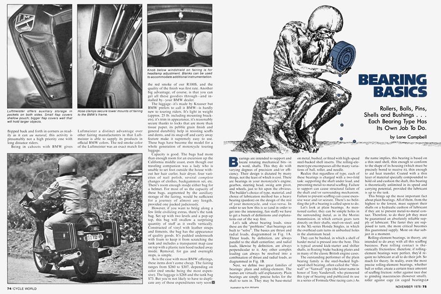
Rollers, Balls, Pins, Shells and Bushings . . . Each Bearing Type Has Its Own Job To Do.
Lane Campbell
Bearings are intended to support and locate rotating mechanical bits-in a word, shafts. This they do with varying degrees of precision and/or efficiency. Their design is dictated by many things, not the least of which is cost. There are bearings in your motorcycle's engine, gearbox, steering head, swing arm pivot, and wheels, just to hit upon the obvious. The builder's choice of type, material, and choice of lubrication method has a heavy bearing (pardon) on the design of the rest of your motorcycle, and vice-versa. In order to see how this is so (and in order to get into the interesting, fun stuff) we have to get a bunch of definitions and explanations out of the way first.
Let's talk about bearing loads, since these are the "problems" that bearings are built to "solve". The basics are thrust and radial loads, diagrammed in Fig. 1A. Thrust loads, by definition, are always parallel to the shaft centerline; and radial loads, likewise by definition, are always perpendicular to it. Any other complex loading can always be resolved into a combination of thrust and radial loads, as diagrammed in Fig. IB.
Next, we define two great families of bearings; plain and rolling-element. The names are virtually self-explanatory. Plain bearings are simply precise holes for the shaft to turn in. They may be base-metal on metal, bushed, or fitted with high-speed steel-backed shell inserts. The rolling-element type encompasses all the many variations of ball, roller, and needle.
Realize that regardless of type, each of these bearings is charged with a two-fold task; supporting the shaft under load, and preventing metal-to-metal scuffing. Failure to support can cause structural failure of the shaft and/or surrounding mechanism. Failure to prevent scuffing can cause excessive wear and/or seizure. There's no belittling the job a bearing is called upon to do.
Let's look at plain bearings. As mentioned earlier, they can be simple holes in the surrounding metal, as in the Morini transmission, in which certain gears turn directly on their shafts, steel-on-steel; and in the XL-series Honda Singles, in which the overhead cam turns in unbushed holes in the aluminum head.
They can be bushed, in which a shell of harder metal is pressed into the bore. This is typical around kick-starter and shifter shafts, in floating brake backing plates and in many of the classic British engine cases.
The outstanding performer of the plain bearing family is the steel-backed highspeed shell bearing, often called the "thinwall" or "Vanwall" type (the latter name in honor of Tony Vandervell. who pioneered this type of bearing and publicized its use in a series of Formula One racing cars.) As the name implies, this bearing is based on a thin steel shell, thin enough to conform to the shape of its housing (which must be precisely bored to receive it), thin enough to aid heat transfer. Coated with a thin layer of material specially compounded to hold oil and cushion the shaft, this bearing is theoretically unlimited in its speed and carrying potential, provided the lubricant is up to the task.
This brings up the most important fact about plain bearings. All of them, from the highest to the lowest, must support their shafts on a hydraulic cushion of lubricant if they are to prevent metal-to-metal contact. Therefore, to do their job they must be guaranteed an absolutely reliable supply of lubricant. The faster they are supposed to turn, the more critical becomes this guaranteed supply. More on that subject in a moment.
Rolling-element bearings, in theory, are intended to do away with all this scuffing business. Pure rolling contact is theoretically frictionless; therefore, if rollingelement bearings were perfect, they'd require no lubricant at all to do their job. So much for theory. In reality, even the most precise rolling-element bearings, whether ball or roller, create a certain trace amount of scuffing friction: roller against race due to grinding inaccuracies (however small), roller against cage (in caged bearings).> roller against roller (in full-complement types), plus some inevitable scuffing of roller-end against thrust face.
Because this incidental scuffing is minimal, so is the need for lubricant. Rollingelement bearings require—in fact, thrive upon—just enough lubricant to keep their elements wet. Over-oiling a high-speed rolling-element bearing can cause churning, rapid heat build-up, excessive drag and possible failure.
Why are there so many types of rollingelement bearings? Mainly because there are so many load/speed/lubricant combinations to cope with. Caged and fullcomplement types were mentioned earlier; let's bear down on them a moment.
A full-complement bearing is one in which the space between inner and outer races has been crammed with as many rolling elements (balls or rollers) as it can hold. These are the ultimate load-carriers. A fully-loaded rolling element bearing (see Fig. 2) is only carrying that load on a few elements at a time. This means that the entire load (and resulting stress) is concentrated on the tiny points at which the rolling elements contact the races. The ability of these tiny points to bear up under stress determines the ultimate loadcarrying capacity of the bearing. When this capacity is exceeded, it causes "brinelling", or permanent deformation of either races or balls/rollers into tiny low spots. When this happens, the bearing develops a "tramp" or shudder, with resultant shock loads that will soon cause the whole works to disintegrate at speed.
Because full-complement bearings place the maximum number of load-carrying points in a given space, they are the champions for ultimate static (i.e., stationary) loading. However, they pay for this strength at speed, for the full-complement rollers constantly bump and rub against each other, creating more churning friction in their lubricant and becoming more vulnerable to scuffing wear.
The caged variety (Fig. 3A and 3B) uses a thin, light floating shell to surround the balls/rollers, keeping them separated and independent while minimizing potential scuffing. What caged bearings lose in ultimate load capacity, they gain in speed potential.
Therefore, the machine designer, looking at possible applications for rollingelement bearings, immediately has a choice determined by load-speed characteristics. High loads, low speeds call for a full-complement bearing. Moderate loads with high speeds call for caged types.
Having chosen caged or full-complement, the designer still has quite a selection of shapes, largely determined by the thrust/radial character of his expected loads. Fig. 4 illustrates the main types of rolling-element bearing with typical loads superimposed. Simple roller and needle types are mostly radial-load bearings; they'll need help to cope with thrust loads. Simple ball bearings can take moderate thrust loads combined with moderate to heavy radial loads. Angular-contact ball bearings and tapered rollers are each designed to cope with heavy thrust/radial load combinations; however, due to their construction, they must generally be combined in opposing pairs.
After toiling through all these bearing types, do you begin to see how they fall into place in various applications on your motorcycle? Take steering heads, for example. Here, we're talking about low velocities—from 0 rpm to the equivalent of 60-100 rpm measured over a short arc. We're talking about bearings that are preloaded in thrust to prevent slop in the mechanism, then subjected to complex dynamic loads reacted up from the tire contact patch. High-load/low-speed immediately calls up the full-complement bearing. A complex of radial/thrust loads calls for either an angular-contact ball (which may be full-complement, and usually is) or a tapered roller (which, for reasons of geometry, must be caged). The lubricant will always be grease, since the stuff stays put, doesn't have to be renewed frequently, and accepts extreme-pressure loads.
How do balls and tapered rollers stack up against each other in the steering head? Cost-wise, the numbers favor the balls; and being full-complement, they have inherently greater load-carrying capacity for a given size bearing. Tapered rollers, since they have "line contact" as opposed to "point contact", (See Fig. 5) tend to spread the loads over a greater area, thus gaining in rigidity, precision, and wear resistance. They will tend to be bulkier and heavier than an equivalent set of balls. (And, yes, there are the obvious advantages of hasslefree assembly, a boon to anyone who has chased dozens of tiny ball bearings around the garage floor. Plus, there are now standard off-shelf tapered rollers with their own built-in outer seals for better grease retention, better environmental protection i.e., dirt and water resistance, hence a longer and cleaner life.)
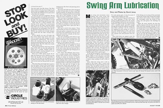
Swing arm pivots (Fig. 6) have some similarity (in terms of velocity) and some basic differences in terms of load reaction. Acceleration and braking loads come in as pure radial loads to the bearing. Side forces to the wheel become thrust/radial complexes at the pivot. In the normal swing arm, side plates and thrust faces are provided to isolate the thrust loads; hence, the pivot bearing is left to deal w ith nearly pure radial loading.
In this mode, either plain bushings or full-complement needle rollers can be used, with grease as a lubricant. The needle rollers are perhaps the ultimate in performance, because they can be assembled with zero slop, are high in load capacity, low in static friction (stiction). They are also expensive and require precision assembly.
At the other end of the spectrum is the plastic bushing, an alternative both praised and damned. A production engineer's dream, the plastic bushing can be one-shot injection-molded by the millions, comes out of the mold ready for use, and the material can be compounded to have its own surface lubricity. On the minus side, the stuff's compressive strength and stiffness can't approach that of even sintered bronze; and since the average highperformance rider is capable of loading it in excess of its compressive stiffness, it is often the culprit in many a high-speed handling problem. Sic transit expediency.
Wheels can be carried on tapered rollers (which, due to complex loading, would seem a natural, but in practice aren't that common) and pairs or ball bearings (the most common). Although simple in appearance, the type of plain ball bearing chosen for wheel support must deal with complex radial/thrust loads. These bearings operate on a "4 point contact" principle, illustrated in Fig. 7. The races are ground to a cross-section that is carefully and deliberately mismatched to the radius of the individual balls. This results in points of contact as shown, which provide a natural load path for complex-angled loads.
Now' we come to the engine-transmission unit, and the fun really begins. First, we can dispense with grease as a lubricant. We're dealing with heat loads and contaminants to be carried away. This calls for a free-flowing lubricant—oil. Oil can be delivered to bearings three ways: dip/ splash, force-feed, and spray-mist. Matching the bearing to the application to the lubrication system can be like playing name your poison.
There are certain principles we can begin with. One is that plain shell bearings, particularly high-speed/high-stress ones, are extremely fussy about their oil supply. Generally, nothing less than pressurized force-feed will do. (I know of one exception that seems to survive in a dip/splash environment; wouldn't you know it's in a Morini transmission.)
Recall that a "cushion" of oil is all that prevents metal-to-metal contact in a plain engine bearing. That cushion, like anything else, has a limiting strength. Part of that strength comes from the oil's ow n film strength; and part comes from hydraulic pressure, which is maintained by the pressurized output of the oil pump. Since oil can constantly weep out around the clearance areas of the bearing (See Fig. 8), this pressurized supply has to be constantly renewed at some volume adequate to replace the loss. This in itself is not a bad thing, for the constant flow of oil through the bearing helps carry off heat.
Another source of oil-cushion strength comes from speed itself. For an explanation, look to Fig. 9. On the shaft there is a layer of oil one or two molecules thick, adhering tightly to the surface. On the journal there is a similar molecular layer; and the two are zipping past each other at whatever linear speed (rpm times bearing> radius~ inches per minute) the shaft is turning. Between them, visualize dozens (hundreds?) of molecular layers like so many stacked sheets of paper slipping against each other. This is how oil behaves in a plain bearing, as long as turbulence doesn't enter the picture.
Now, the way the fluid dynamics of the thing work out, these slipping layers create a pressure buildup just ahead of the nar rowest portion of the shaft/journal clear ance area, which also, conveniently, happens to be where journal and shaft are squeezed together by radial loads. Note that as load direction changes, so does the position of the pressure bulge, and that the effect increases with speed, up to a pretty high effective rpm-limit. It's this phe nomenon that gives the plain bearing some excellent high-speed capabilities.
In fact, tests have shown that a properly designed, lubricated, installed plain bear ing has less high-speed drag than a com parable roller bearing. The roller will have less stiction. The plain bearing will be lighter and more compact for a given dynamic load capacity.
It almost sounds as though the plain bearing is superior to the rolling-element type, doesn't it? Then how come all the hoorah. in advertising and elsewhere. about ball-and-roller engines being so spe cial? On examination, it turns out to be not so much a matter of best as a matter of practicality. (Although there's been occa sion to speculate that some Japanese four-
stroke motors have been specified as balland-roller designs because the marketing department told the engineering depart ment that was what those crazy Americans wanted.)
We've already said that plain shell bear ings are fussy about their lubricant. Roll ing element bearings tend to be much less so. They can live comfortably in a dip/ splash environment (hence find their way into extensive gearbox/primary drive use): and if force-fed, they prefer their oil in small doses.
They particularly love a spray-mist. I found this out delving through needlebearing factory specs. while helping Crazy Ollie the Neanderthal (a riding buddy some years back) attempt the design of a world-beater engine.
The specs go like this-they give you the size, static load capacity. limiting speed, and a thing called "B-50 life". B-SO life is the number of operating hours at which you have a 50-50 statistical chance of a shot bearing. This life varies with speed and dynamic load, sometimes rather dras tically. All through the spec book were the following cryptic phrases: "These figures typical for full-flow oil-lubricated installa tions. Spray-mist lubrication can increase B-SO life by threefold, sometimes more. Please contact our engineering depart ment for further info."
Upon a little thought. it became pretty evident. A fine mist provides just enough oil to keep the elements wet, no more. And
it has a definite cooling effect. Because a two-stroke motorcycle engine's crankcase is an environment of air/oil/fuel mist, is it any wonder that these motors run almost exclusively on ball-and-roller lower ends?
What of the various four-stroke designs? Historically, ball-and-roller designs have been used when oil supply could be con sidered marginal. From the beginning, a motorcycle engine has been a bare-bones device: and for whatever reason, adequate oil pumps were among the last bits tacked on to the basic mechanism. Not that good pumps are anything new-Triumphs have scavenged their dry sumps and fed their plain shell bearings with an excellent twostage pump design that dates back 40 years. You might say that the presence or absence of a full-pressure. full-flow oil system reflected the designers' order of priorities.
Today there is certainly no such excuse, as we have `~gerotor" trochoid type pumps capable of living forever and exceeding any engine's demands. On the modern motorcycle, bearing choice becomes inter twined with crankshaft construction and overall cost-effectiveness for a given en gine design.
Realize that if you're building your en gine around a one-piece crank. you've got to use split bearings in order to assemble the rods to the beast. (See Fig. 1OA) Plain shell bearings split easily; but caged roll ing-element engine bearings, as they come from the factory. are essentially one-piece gadgets.
Ah-hmm. Now it begins to dawn. A caged-roller big-end is going to have to run in a one-piece rod, slipped over the crankpin of a pressed-together crank. (See Fig. 10B). Crankcases can be horizontally split around rolling-element bearings; and often are, to ease drop-in assembly. However, a multi-cylinder, multi-throw roller crank still has to be built up as a series of single-cylinder pressed-together cranks which are in turn joined together with their main bearings between.
Two-strokes almost have to be built this way. With a four-stroke it almost seems crazy to go to all this complexity if a onepiece crank will do the job. Still, designers do it both ways, and production engineering has a lot to do with the choice.
There are two ways to make a highstrength one-piece crank. One is to machine it the hard way, starting with a large, hard alloy steel billet. Very time-consuming, plus you leave most of your billet on the floor as chips. The other way is to dieforge the complete crank and then finishmachine the pins. This has proven the best in practice. It's quick, repeatable, conserves material, and creates a highstrength product.
However, as you go away from simple single-throw' and in-line twin throw designs, forging can become complicated. This is because the dies (See Fig. 11) should split along a single plane for best results. So, how do you make a 120-degree three-plane crank for a triple? (See Fig. 12). There are two ways. One, you can forge the whole thing in one plane, then twist the throws into the desired relationship with a second set of dies. Two, you can use a complex of multi-stage dies to forge the crank by sections, ending up with the desired piece after several "hits". These are definitely mass-producer processes, calling for high-buck tooling and lots of engineering manpower during the design stages. For some firms, it is easier to order up pairs of forged crank-halves from one source and precision-ground crankpins from another source, then press together the pieces. The Big Four have done it both ways, each for their own inscrutable reasons. Do Honda Fours have one-piece cranks because they have plain shell bearings, or vice-versa? Interesting conjecture, wot? The only certainty is when you have one, you've gotta have the other.
I have only seen one instance in which a roller big-end bearing has been fitted to a split rod on a one-piece crank. It's not on a motorcycle engine, but it's close enough to be interesting. Anybody who used to race karts ought to have guessed already; it's the ubiquitous lOOcc McCullough chainsaw motor.
They machine their rod in one piece, carefully grind an outer race in the rod's bore, then precisely fracture (yes, I said fracture) the rod's lower end. It's designed to go "ping" in precisely the right spot when hit. They assemble this rod around a full complement of needles on a one-piece crank. By all rights, those needles should rub and joggle each other to death at the 10.000-plus rpm speeds we were turning in 1962-63, but they didn't. Part of it was your good 'ol spray mist to the rescue. Part of it w'as just a fortunately tiny bearing. Little ones have higher limiting rpms than big ones.
Because we've gone along talking of needle-roller rod bearings, it follows that rod big-ends take mostly radial loads. What thrust loads there are will come from misalignment, or from transient shock loads to the whole engine unit (as when the entire bike/rider comes down sideways and out-of-shape). Thrust faces and/or thrust washers may be provided at either the big-end or small-end to cope with these loads and maintain alignment, leaving the bearing totally radial-loaded.
Because the rod big-end swings through an arc with the crankpin, its weight and bulk are critical to engine balance and smoothness. Plain shell bearings are, in themselves, lightest and most compact. However, a split rod tends to eat up that advantage. If a roller big-end is chosen, the needle roller is the lightest, most compact unit available.
Note that most two-stroke motors have a full-complement needle bearing at the small-end also, while in most four-stroke motors, (even the roller-crank variety) the small-end is bushed. The choice is a matter of lubricant supply; the two-stroke de->+ \signer is simply taking advantage of the spray-mist environment inside the crankcase.
Roller-crank main bearings have to deal with greater thrust loads than rod bearings. Helical spur primary drive gears can place a heavy thrust load on the crank's driving end. Even without that source, there's the problem of case expansion. Since cranks are invariably steel and cases are invariably aluminum, the case "grows" about three times faster than the crank when heated.
Different designers deal with this in different ways. Eve seen some motors with ball-bearing mains on both ends of the crank. This means that as the case expands, it puts thrust loads on both bearings, which are designed to take it. It also puts a slight bending pre-load on the crank, which also must be designed to take it.
Other motors use a ball at one end and a roller at the other. The ball bearing (usually located next to the output end of the crank) takes combination radial and thrust loads in order to keep the crank positively located in the cases. The other end semifloats in the roller bearing, free to slip within a limited range as the cases expand, while the bearing itself is loaded radialonly. Both setups work—what more can one say?
An all-plain bearing motor has the same sort of problems. Thrust faces have to be
provided on the rod and the crank to maintain alignment: for alignment is critical if a plain bearing is to maintain its supporting oil cushion. In a single-cylinder or V-Twin motor, there is usually positive thrust location on one end of the crank while the other is free to float in its bearing.
You can usually tell if a plain shell bearing has been designed to take heavy thrust loads; it will have a thrust face w'rapped around one or both sides. That's generally your "locater". The rest will be "floaters", within some limited range.
Twins and multis with three or more main bearings get a bit hairy. Because different parts of the case and crank are going to expand at slightly different rates, there must be just the right amount of endplay at each main bearing.
Think of it like this: (See Fig. 13). If a bearing at one end of the crank is positively located, the bearing next to it will be displaced "x" distance by thermal expansion in a hot engine. The next throw down the line will be displaced "2x" and so on.
If thermal expansion displaces a bearing beyond its designed range of float, two things will happen. First, a bending load will be reacted into the crank itself. Second, that bending load will get reacted into the oil film in the bearing as an off-center, off-balance load, causing turbulence in the oil film. Turbulence and whorls in the bearing's oil film cause hot-spots and local dry-spots, which in turn cause instant lunched bearing. (See Fig. 14).
Now' you know why. in the early stages of a multi's development, cranks tend to go "blooey!" until the designers get the crankshaft dimensions exactly right. Once they settle those right dimensions into normal production tolerances, it's a piece of cake (it says here . . .).
Honda has a machine that cranks out (oops, did it again) 900 four-cylinder crankshafts per work-shift, untouched by human hands. When you begin to appreciate the problems they've solved in order to achieve this with reliability, you've got to respect them.
In fact, the more you know' about bearings and the jobs they're called upon to do. the more you have to respect the generations of skull-sweat that have gone into their design, regardless of nationality. Be it plain or roller, each one is a tiny, massproduced precision unit. Each bearing is designed for specific lubrication requirements within a specific load/speed environment.
What I've tried to lay out on these pages is far from an exhaustive treatment of the little buggers. Still, with an appreciation of what goes into them, and what they do. you'll in turn appreciate that of scooter a bit more and better understand what lubricants it requires, where, and how often. For that, your bike and your body may both be thankful.