"Seeing" Ignition Work
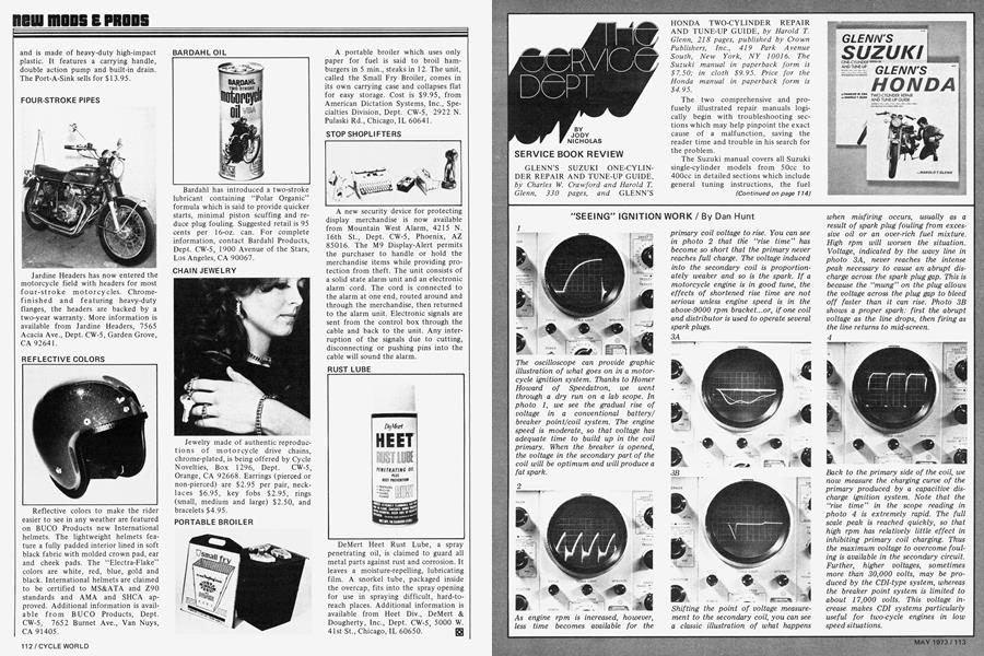
"SEEING" IGNITION WORK
Dan Hunt
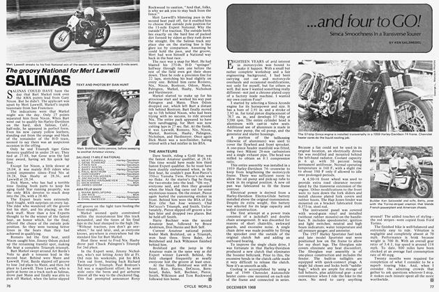
The oscilloscope can provide graphic illustration of what goes on in a motorcycle ignition system. Thanks to Homer Howard of Speedatron, we went through a dry run on a lab scope. In photo 1, we see the gradual rise of voltage in a conventional battery/ breaker point/coil system. The engine speed is moderate, so that voltage has adequate time to build up in the coil primary. When the breaker is opened, the voltage in the secondary part of the coil will be optimum and will produce a fat spark.
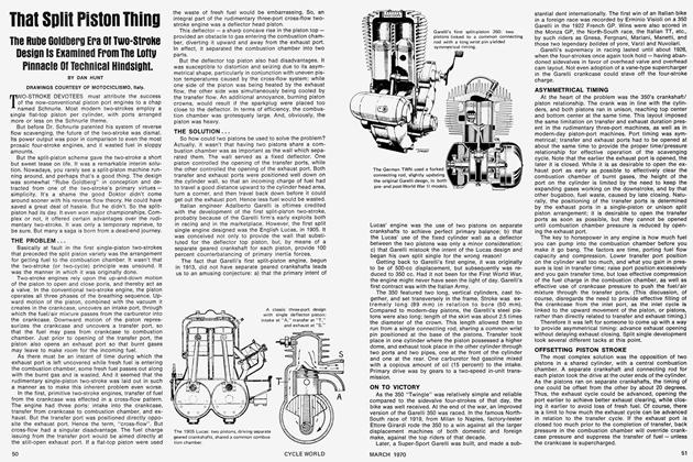
As engine rpm is increased, however, less time becomes available for the primary coil voltage to rise. You can see in photo 2 that the "rise time" has become so short that the primary never reaches full charge. The voltage induced into the secondary coil is proportion ately weaker and so is the spark. If a motorcycle engine is in good tune, the effects of shortened rise time are not serious unless engine speed is in the above-9000 rpm bracket...or, if one coil and distributor is used to operate several spark plugs.
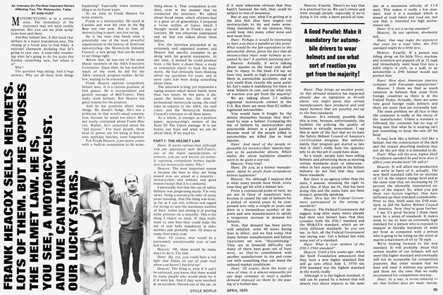
Shifting the point of voltage measure ment to the secondary coil, you can see a classic illustration of what happens when misfiring occurs, usually as a result of spark plug fouling from exces sive oil or an over-rich fuel mixture. High rpm will worsen the situation. Voltage, indicated by the wavy line in photo 3A, never reaches the intense peak necessary to cause an abrupt dis charge across the spark plug gap. This is because the "mung" on the plug allows the voltage across the plug gap to bleed off faster than it can rise. Photo 3B shows a proper spark: first the abrupt voltage as the line drops, then firing as the line returns to mid-screen.
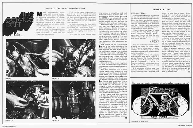
Back to the primary side of the coil, we now measure the charging curve of the primary produced by a capacitive dis charge ignition system. Note that the "rise time" in the scope reading in photo 4 is extremely rapid. The full scale peak is reached quickly, so that high rpm has relatively little effect in inhibiting primary coil charging. Thus the maximum voltage to overcome foul ing is available in the secondary circuit. Further, higher voltages, sometimes more than 30,000 volts, may be pro duced by the CDI-type system, whereas the breaker point system is limited to about 17,000 volts. This voltage in crease makes CDI systems particularly useful for two-cycle engines in low speed situations.