Two Strokes
TWO STROKES
Part Three, And Conclusion
GORDON H. JENNINGS
THUS FAR, in this series on the two-stroke engine, we have covered overall fundamentals, and have gone into combustion chambers and cooling. Among the things explained was the fact that vast benefits can be gained by employing the highest possible compression ratio — and that if this is carried too far, the engine will fail. Also, we established the worth of improved cooling, such as may be had by using aluminum, with its ultra-rapid heat transferring properties, in the construction of cylinders. And, we gave some mention to the desirability of water-cooling in high-output, two-stroke engines.
All of these things are important, as they make possible the fullest use of the fuel and air that is being pumped through the engine. However, they are all to no avail if the engine is unable to “breath" properly. Horsepower is, after all, very directly related to the quantity of air an engine is able to process per unit of time. It has been said, and with some truth, that power output is independent of displacement, which means that there is no limit in sight to the amount of power that can be wrung from an engine. To get more power, one need only increase the engine's speed. Of course, increased friction will rob part of the power gained by turning the engine faster, but not enough to pose any real problem. In the end, it will be the various resistances to air-flow that put the ceiling on power and the success of any tuning operation will depend to a great extent on how much the tuner has improved the engine as an air-pump.
In the case of the crankcase-scavenged two-stroke engine, the air pumping is done by the same piston that transmits thrust from the burning fuel/air mixture. It should be made clear, right at the start, that the crankcase pump can only be made to move just so much air — no matter how elaborate the valve system or how small the clearance volume. After all, only a volume of air equal to the piston displacement can ever be drawn into the crankcase. That is to say: in a 15 cu. in. engine, no more than 15 cubic inches of air can be pumped through in a single revolution. A great deal of nonsense has been written about “stuffing" crankcases, but in point of fact even if a crankcase has the interior dimensions of a barn and a pin-hole intake port, moving the piston upward to displace 15 cubic inches will eventually result in 15 cubic inches of air being drawn in.
The only reason for increasing port area and reducing the crankcase clearance volume is to move the air more rapidly. Once enough area and pressure has been provided to achieve 100 percent pumping efficiency, there is absolutely nothing to be gained by further increases. In practical terms this all boils down to one thing: increases in area and pressure will not improve
power output unless there is a matching increase in engine speed. Indeed, there may even be a loss in performance.
Pumping work done in the crankcase is not “free"; it must be paid for in terms of resistance to piston movements, and some of the total effort provided by the expansion of the burning mixture is lost. This reduces power output to some extent, but the most noticeable loss is in torque. The pressure on the underside of the piston tends to balance that from above and there is an appreciable drop in low-speed torque as a result. Thus, it is fruitless to raise the pumping pressure beyond what is actually required to move the volume of air in the time available.
When substantial increases in operating speed are contemplated, improvements in pumping speed are, of course, certainly indicated. Reductions in clearance volume are one means to this end, but in some engines it is quite difficult to bring about much of an improvement. Many motorcycle engines have full-circle flywheels, and efforts at filling-in will have to be restricted to small corners. Do not make the mistake of fitting staffer blocks that restrict the airflow. It is all too easy to lose more than is gained by going too far.
One technique we have seen is the filling of the piston interior. This strikes us as being a very poor idea. Perhaps in an engine using cross-flow scavenging and having a deflector-crown piston the idea has some merit, but most motorcycle engines have nearly flat pistoncrowns, which limits the amount of filling possible, and heat dissipation from the puttied-in area is poor.
Some engines do not have full-circle flywheels, and in these it is possible to better things a lot. Really ambitious tuners can simply machine a new crankshaft assembly, with full-circle flywheels that have closed-off balance holes. Lacking that much ambition, or money resources, packing pieces — preferably of aluminum and hollow — can be added where the flywheels have been trimmed for balance. When this is done, it should be remembered that some re-balancing may be necessary.
One small touch that certainly merits consideration when working inside the crankcase is the polishing of all surfaces. The air inside the crankcase is moving about at high speed and it will move quicker and pick up less heat if the surfaces with which it comes in contact are smooth. The polishing can be extended to include the connecting rod; a smooth surface is less apt to develop cracks that might lead to a total break. Do not polish inside the piston: it is doubtful that anything will be gained in crack resistance, and this is one component from which heat should be removed by any means available.
Piston cooling is one of the several factors that leads us to favor transfer porting that takes the airflow through a window in the piston skirt. When this is done, the cool mixture scours heat from the underside of the piston and reliability cannot but be improved.
While on the subject of pistons, we would like to point out that in the two-stroke there are special conditions to be met. First off: the two stroke piston can have its skirt trimmed only slightly for lightness. Enough must always be left to mask the exhaust port when the piston is at top center or exhaust gases can be drawn in to dilute the fresh mixture. In engines having a pistoncontrolled intake port (as most do) the skirt cannot be trimmed in the port area without affecting the intake timing. Finally, it seems to us that, considering the effectiveness of the modem piston ring, the racing engine should not have more than one ring. A single, thin ring can do the job of gas sealing adequately, and the saving in friction from ring drag is considerable. Here again, the perfectionist in search of the last bit of power can, at some expense in time and energy, secure a slight advantage over those not quite so determined. There is a special type of piston ring, with an “L” shaped section, that gives the greatest cylinder wall contact area and the best sealing for the least weight. This is the Dykes-pattern ring, to give it its proper name. Standard rings can be modified to this pattern by clamping them in a fixture and machining away part of the upper back of the ring. However, as these L-section rings must be used in a piston groove of the same shape, a special piston will have to be made as well.
Getting the mixture into the crankcase is a problem in high-speed engines. When the piston-controlled port is used, the period during which the mixture is actually flowing into the cylinder is extremely brief. The port is, after all, opened and closed much faster than a camera shutter and the mixture must move fast, or it will not be able to move at all. Thus, intake port and carburetor throat areas must be made very large — much larger than would be needed for a four-stroke engine of comparable size. For example, racing two-strokes of only 125 cubic centimeters will have carburetor throats ranging from 1-inch (which we consider a lower limit) all the way up to 1 3/16-inch. By comparison, the same throat size will be found on highly tuned four-strokes of 350-500 cubic centimeters in capacity. The reason is simply that the four-stroke draws in its mixture relatively gradually, while the two-stroke takes it in quick gulps. We would recommend 1 1/8-inch carburetors for racing 125cc engines. A 250 will, of course, not have double that size because area increases faster than diameter and, also, because a 250 will not turn as fast as a 125. We are, obviously, referring to unit cylinder sizes; a 250 consisting of a pair of 125 cylinders must be treated for what it is: two separate 125 engines.
In the port itself, and in the intake passage leading to the port, production-type engines generally have plenty of room for improvement. Often, it will be best to remove the cast-on intake pipe entirely and substitute a larger pipe. The new pipe can be attached by welding (if you can find someone who is good enough to do the job and if the cylinder material will permit) or, better yet, some form of bolt-on attachment can be made. The new intake pipe should form a smooth “leadin” from the carburetor to the port, and a heat-blocking gasket between the cylinder and the pipe is a good idea. The pipe, which will be roughly conical in shape, may be machined from solid material, or cast, but most people will find it easiest and most satisfactory to fabricate it from light-gauge sheet metal.
In most two-strokes using the piston controlled intake port, the bottom edge of the port opening, which is the opening edge, has a sharp, V-shaped dip at its center. The purpose of this dip is to reduce the port opening rate and by, in effect, opening more slowly, draw in the mixture more gradually. This tends to quiet the natural noisiness of the two-stroke’s induction process. Noise is, of course, no problem in a racing engine, and a good start in intake port modification can be made by lowering the edge of the port down to the level of the dip. The upper edge of the port may be raised only as high as the lower edge of the piston skirt when the piston is at top center. And, it is generally unwise to raise the upper edge of the port at all if by so doing the top of the piston comes down below the port. This will give a direct opening between the intake tract and the cylinder, and unless both intake and exhaust systems are carefully tuned to create a flow from the intake pipe into the cylinder as the piston’s upper edge clears the port, a drop in power can be the result.
Extreme care must also be exercised in widening the port. The piston ring, or rings, must pass over the port opening and if it is too wide, the rings will bulge out into the port and when the piston moves upward again, the rings will be broken. Sometimes, when a port has been widened too much, the tendency to break rings can be relieved slightly by chamfering the upper edge of the port opening. This chamfer will, if the ring-bulge is not too severe, gather in the rings and tuck them into place as the piston goes up. The only certain method for determining the critical width is to exceed it. When the rings begin to break, you will know that the port is too wide. A new cylinder, with a port slightly narrower, is the answer. If you have no wish to spend money on extra cylinders, we would suggest that the port be left very near its stock width.
Experiments in intake timing can be conducted by gradual trimming of the piston skirt in the intake port area. This will open the port sooner, and hold it open longer, and after many cut-and-try sessions, you will be able to determine the timing that gives the most power over the engine speed range jn which you are interested. When the timing has been determined in this fashion, the lower edge of the port can be lowered by a distance that will give the same intake timing with a solid-skirt piston. You may be thinking “why not just use the piston with the skirt cut-out and leave the port alone?” The reason is that all the skirt cutaway does is increase the period during which the port is open, while lowering the edge of the port increases both the open period and the port area as well.
A factor that should not be overlooked when these port modifications are being made is that raising the power output has a narrowing effect on the power range as a whole. An engine that, in stock form, produced over 10 bhp through an engine speed band extending from 3000 rpm to 6000 rpm, with a peak of 15 bhp at 5000 rpm, may after being modified have an attractive 20 bhp at 6500 rpm, but have only 8 bhp at 6000 rpm and even less at 7000 rpm. When this happens, it is almost certain that the performance at the 15 bhp level will be better than that given by 20 bhp. A touring-type transmission, with relatively widely spaced ratios, cannot be used to hold the engine speed within the narrow band where the higher power is being developed. Therefore, do not embark on any extensive engine modification program unless close-ratio gearing is included in the planning.
For the tuner with money and/or machine-shop facilities, the possibility of abandoning the piston-controlled port for a rotary-type intake valve should not be overlooked. Rotary intake valves can take several forms, but the variety most suitable for racing engines is the disc-type valve, in which a thin plate, rotating with the crankshaft, opens and closes the port. The disc is usually situated in one end of the crankcase and runs in a narrow space between the crankcase wall and a cover plate. The disc has a portion of its periphery trimmed away and is oriented so that the solid section of the disc blocks the intake passage (which goes through the cover plate and the crankcase) when the piston is on its down stroke and uncovers the port opening when the piston goes up. The intake period can thus be extended much more than is possible with the piston-controlled port, and the timing need not be symmetrical. These characteristics offer the chance to have good high speed filling without too-drastically reducing the width of the power band. A very few companies are beginning to use the rotary intake valve, Yamaha being the most prominent example that comes to mind, but we may logically expect to see it more often.
Before leaving the crankcase, it might be wise to mention lubrication. A two-stroke engine is a very scantily oiled piece of machinery — higher percentages of oil in the fuel being provided only at some cost in power — and we must make the most of every drop. One of the means to this desirable end is to chamfer the outer edges of the lubrication slots present in most two-stroke connecting rods, which will allow a bit more oil to reach the rod bearing. Another is to smooth the entrance leading into the oil-feed holes for the main bearings. Also, there is a thing or two to be done in the selection of oils. When using mineral oil, stick to 50W; it will clog the exhaust port rather badly, and frequent cleaning may be necessary, but the bearings will love the stuff. Castor oil, which some people favor, is also very good, but only the best grade AAA degummed oil should ever be used. When using alcohol fuels, castor oil is especially good because it will mix readily and mineral oil may not. Gasoline will, of course, always mix with mineral oils but may not with castor oils. Sometimes, when the fuel and oil will not easily blend, a small quantity of acetone (one or two percent) will help. And, particularly when racing, the fuel and oil should not be just dumped into the tank; instead, put accurately measured portions of each into a large can and shake until thoroughly mixed. Any time experimenting with fuel/oil mixtures is done, samples of the mixture should be made up and allowed to stand in jars for several days to determine if they will stay mixed.
After the mixture is drawn into the crankcase and compressed, it must still be transferred into the cylinder, and this is a most difficult thing to accomplish in the time available. Even in the very highly tuned MZ racing two-stroke, the transfer ports are only open through 125 degrees of crank-angle, and at 10,000 rpm the port just flickers open and then closes again. Moreover, the open period cannot be extended because to do so would be to rob too much from the power stroke. Oddly enough, the transfer port timing of the most mildlytuned touring engine will not be too much less in duration than the racing MZ. In fact, a study of the exampies we have at hand indicates that transfer timing will always be between 110 and 130 degrees in duration. That is, you will note, not much of a spread and we have come to the conclusion that the transfer ports are best left at their stock height. Raising their upper edges enough to be worthwhile, in terms of increased port area, would certainly extend the transfer duration beyond the 130 degrees of the most highly tuned racing engines.
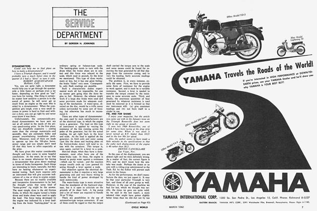
Even though the port height should not be altered, a great deal of effort may be expended — and to good effect — in polishing and shaping the interior of the transfer ports. However, unless one is prepared to go all-out on this job, it is best never started. The trick is to get a glassy finish inside the transfer ports, while providing a shape that will direct the streams of mixture across the top of the piston and against the back of the cylinder wall with absolute symmetry. The mixture streams should converge, at an included angle that will range from 120 to 130 degrees in most engines, just ahead of the cylinder wall and climb, in a straight line, up into the cylinder head. Never bevel the roof of the transfer port so that the mixture in directed upward; that will surely result in a loss of power. Occasionally, 10 or 15 degrees of slope may be used to direct the mixture streams over the top of a domed piston, but one must always be very careful in doing this. Also, sloping the port will reduce its effective height by leading the flow through obliquely.
Flow patterns within the cylinder may be checked by cleaning the combustion chamber and the top of the piston carefully and then running the engine under a light load for 30 minutes or so. After this is done, the upper end of the engine is dismantled and there should be tracings in the carbon deposits to show the flow pattern. Examine particularly the tracings on the piston head; they should indicate a symmetrical pattern from the ports and toward the cylinder wall.
This method of determining flow is, obviously, rather time consuming and the really devoted tuner of twostrokes might find it profitable to build a test rig to do the job. Such rigs could take many forms, but it seems to us as though a “lucite” cylinder head (without cooling fins, of course) could be made that would permit observations of gas flow within the cylinder. Then, the cylinder, with the piston in place, could be set on a stand, with a vacuum-cleaner connected to the exhaust port, which would pull air into the cylinder from the transfer ports. With the air in motion, a spray of dye could be introduced into the transfer ports and the streaks left on the cylinder walls, piston, and combustion chamber would give a graphic record of flow. Naturally, this method would also work with the standard cylinder head in place, but then one could not actually watch the process.
At the exhaust port, there is slightly more latitude for modification. These, like the intake port, will sometimes have a notch (in their upper edge) to allow the exhaust to escape relatively slowly and thereby avoid the sharp cracking sound produced by rapidly escaping gases. A few engines will have a slanted upper edge on the exhaust port, the purpose being to produce the same slowopening effects. For racing, the exhaust port’s upper edge may be brought up level. The port may be widened slightly, but the same danger of broken rings exists as is the case with the intake port. Do not lower the port; if this is done, the piston skirt may clear the port and allow some of the exhaust gases to be drawn back into the crankcase.
As a rough guide for exhaust port timing, we consider a duration of 140 degrees to be mild, and as much as 180 degrees have been used in ultra high-speed racing engines. Probably, the average modified touring engine would not need more than 165 degrees of duration. The exact amount would, naturally, depend upon the transfer port timing and the engine speed anticipated.
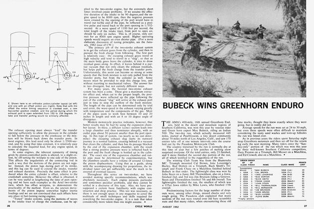
The exhaust opening must always “lead” the transfer opening sufficiently to allow the pressure in the cylinder to fall below the pressure in the crankcase or the mixture will be blown back down the transfer ports. In most engines, this lead need only be about 1/2500-second, and by using that time constant, it is relatively easy to calculate the required lead, for any engine speed, in terms of degrees.
In some engines, the inherent symmetry of timing given by piston-controlled ports is altered, to a slight extent, by off-setting the wristpin to one side of the piston. This affects the angularities of the connecting rod in such a way that the motions of the piston are not regular. Instead, the piston lags during part of its stroke, and this lag can be used to extend the intake, transfer and exhaust duration. Precisely the same effect is produced when the entire cylinder is offset, relative to the crankshaft centerline. However the offset is obtained, it can be very useful in lengthening the time of port opening and we have such examples as the Ariel two-stroke twin, which has offset wristpins, to demonstrate the practicality of the method. Even so, the uneven movements of the piston impose somewhat higher inertia loadings and we are not convinced that such offsets have any place in fast-turning racing engines.
“Tuned” intake systems, using the motions of waves in the intake tract to charge the crankcase, can be applied to the two-stroke engine, but the extremely short times involved create problems. If we assume the effective duration of the intake to be 90 degrees,and the engine speed to be 8000 rpm, then the negative pressure wave created by the opening of the port would have to travel out U>the end of the pipe, be reflected as a positive pulse .and travel back to the port opening in 1/532second. At a wave speed of 1100 feet per second, the total length of the intake tract, from port to open air, should be only six inches. This is, of course, only correct for an 8000 rpm engine speed. Higher operating speeds would require an even shorter pipe. (For a more elaborate discussion of tuning principles, see the January, 1962 issue of CW.)
The primary job of the two-stroke exhaust system is to get the exhaust gases from the cylinder, and then to prevent the fresh charge from following. The first part is relatively easy: the escaping exhaust gases travel at high velocity and tend to travel in a “slug”, so that as the main body gases leave the cylinder, it tries to draw residual gases along. In effect, it leaves behind it a partial vacuum that not only clears the exhaust residuals, but helps pull the fresh charge from the transfer ports. Unfortunately, this assist can become so strong at some speeds that the fresh mixture is not only pulled from the transfer ports, but fropi the cylinder as well. Some means must be provided to stop this charge loss, and without resorting to mechanical valves. The answer lies in two divergent, but not entirely different ways.
For many years, the favored two-stroke exhaust system has been a cone. These give a maximum extractor effect and, when cut to the proper length, the positive pressure wave reflected up the pipe following the exit of the exhaust “slug” will arrive at the exhaust port just in time to stop the outflow of the fresh mixture. The length of the pipe can be determined only by trial and error, the wave-speed in the exhaust varying greatly with temperature and the components of the gas. Most of the pipes seem to work best between 10 and 20 inches in length and with an 8 or 10 degree angle of divergence.
Modern motorcycle practice indicates, however, that better results may be had by using the expansion chamber layout. In these, a diffusor (cone) section leads into a large chamber and then terminates abruptly, with an outlet pipe about 50 percent smaller than the port opening. In this type of system, (as nearly as we can determine) the escaping exhaust slug starts its outward journey in a normal fashion, creating behind it a vacuum that clears the cylinder, and then has its passage blocked by the end of the expansion chamber, with the result that a strong positive pressure wave is reflected back to the port and the fresh charge is bottled up in the cylinder. The exact size of the expansion chamber and outlet pipe must be determined by experimentation, but the chambers usually have a volume of around 12-times the piston displacement. Using that as a guide, along with the accompanying drawing for proportions, the individual tuner can get sufficiently near the mark to be assured of eventual success.
Throughout this series on two-strokes, we have avoided making specific recommendations, which was absolutely necessary. Each engine presents particular and sometimes peculiar problems, and they cannot be settled in a discourse of this type. Also, we have presupposed a certain basic familiarity with engine construction and shop practice. This too was necessary, as there is not enough space in any magazine to cover the multitude of small techniques and skills required for reworking the two-stroke engine. It is a task that takes considerably more talent than one might assume. •