ELEMENTS OF FUELING
ELEMENTS
Keeping engine fuel-air ratio correct
KEVIN CAMERON
Fueling is turn-key in our digital era. The fuel injectors under the throttle plates of modern bikes are solenoid-operated fuel valves with multi-hole nozzles that produce timed sprays of fine droplets. Because fuel pressure is held constant by a submerged electric pump, the amount of fuel delivered is easily controlled by how many milliseconds the ECU holds an injector open.
Before injection, fueling was analog, and the device we used was a carburetor. Despite expressions like “give it the gas,” what we control with the throttle is not fuel flow but airflow. Fuel flows passively in response to the partial vacuum created by air moving past fuel orifices in the carburetor’s air passage. Because electric sparks cannot ignite gasoline/air mixtures outside the range of 18-to-l to 10-to-l, and because best power occurs at about 12-to-l, accurate mixture control is essential to power and fuel economy.
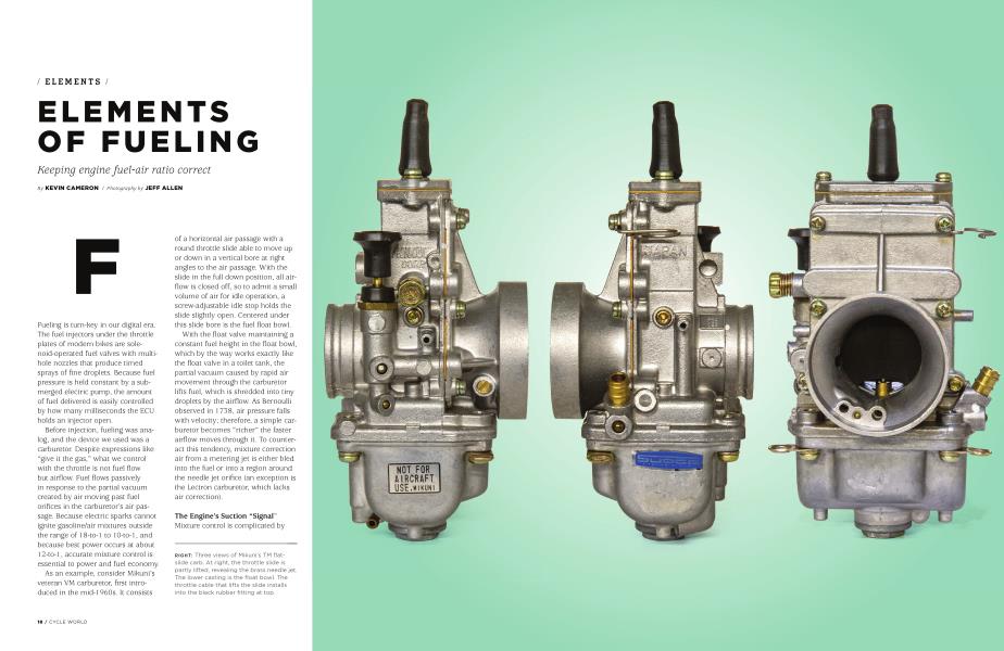
As an example, consider Mikuni’s veteran VM carburetor, first introduced in the mid-1 960s. It consists of a horizontal air passage with a round throttle slide able to move up or down in a vertical bore at right angles to the air passage. With the slide in the full down position, all airflow is closed off, so to admit a small volume of air for idle operation, a screw-adjustable idle stop holds the slide slightly open. Centered under this slide bore is the fuel float bowl.
With the float valve maintaining a constant fuel height in the float bowl, which by the way works exactly like the float valve in a toilet tank, the partial vacuum caused by rapid air movement through the carburetor lifts fuel, which is shredded into tiny droplets by the airflow. As Bernoulli observed in 1 738, air pressure falls with velocity; therefore, a simple carburetor becomes “richer” the faster airflow moves through it. To counteract this tendency, mixture correction air from a metering jet is either bled into the fuel or into a region around the needle jet orifice (an exception is the Lectron carburetor, which lacks air correction).
The Engine’s Suction “Signal” Mixture control is complicated by the fact that engine cylinders take their mixture in intermittent gulps rather than as a steady flow. These gulps create what is called “vacuum signal” or just “signal” at the fuel outlets. Sharp, sudden gulps pull more fuel through jets than do longer, smoother, or lower-amplitude intake impulses. Strange though it sounds, this causes the same carburetor size, when used on cylinders of different displacements, to need smaller jets the bigger the cylinder is. This effect also applies to intake timing. A long, gradual intake process typically draws less fuel from a given carburetor than does a shorter, sharper intake event on a given cylinder displacement.
How a Carburetor Controls Air-Fuel Mixture
As the throttle slide is lifted from the idle position, air-fuel mixture is controlled by four overlapping aspects of carburetor geometry.
Idle and initial throttle. Fuel is delivered through a separate idle jet, feeding orifices drilled in the bottom of the air passage near the closing (downstream) edge of the air slide. Throttle slides may be round, flat, or oval.
Further slide lift allows more airflow whose partial vacuum begins to lift fuel from the main system’s needle jet, located centrally under the throttle slide. In this regime, mixture is controlled by the shape of the underside of the slide. To adjust the partial vacuum produced by airflow under the slide, the slide’s leading edge is made higher than its trailing (closing) edge. This height difference is called slide cutaway. Mixture during the first quarter or so of slide lift is controlled by cutaway; the lower the cutaway, the richer the mixture.
As the slide lifts beyond quarter throttle, the main determinant of fuel flow becomes the orifice formed between the needle jet (set into the floor of the air passage and centered under the air slide) and the tapered jet needle, which is attached to and rises with the throttle slide. Needles are made in a variety of tapers, and needle jets in a variety of bore diameters.
From three-quarters to full throttle, the main determinant of fuel flow becomes the main jet, which is screwed into the bottom of the needle jet, submerged in fuel near the bottom of the float bowl.
If the engine runs well on steady throttle but hesitates or misfires when the throttle is moved rapidly, suspect leanness in No. 2 above. Fuel, being 600 times heavier than air, lags behind when the throttle is snapped.
Although the various makes and models of slide carburetor, Keihin, Amal, Dell’Orto, etc., differ in the details of individual parts, the basics are common to all. The Lectron and certain other specialty carbs deliver all their fuel from a single system and so lack a separate idle system.
Cold starting requires mixture enrichment, because the engine is too cold to evaporate all the fuel, and carburetor design provides the means for this. On Japanese designs a miniature starting carb is built into the main casting. In older British designs a “finger” is lowered into the airway from above, reducing airflow and thus providing enrichment.
Is There Adequate Fuel Flow Capacity?
In order for fuel to flow from the tank, air must enter to replace it. A tank vent or air orifice in the fuel cap must be clear. A screen or filter element may be built into the fuel petcock: Is it blocked by rust or other sediment? If so, particulates inside the tank must be removed as well. The carburetor’s float valve, controlled by the rise and fall of the float, must be large enough for the application. In the Mikuni system a 1.5 float valve is only for operation with a fuel pump. For gravity feed, numbers such as 2.5 or larger are usual.
Can the fuel system keep up with engine demand? A four-stroke engine needs roughly half a pound of fuel per horsepower, per hour. If your engine makes 100 peak horsepower, its fuel system must deliver a minimum of 50 pounds of fuel per hour (8 gallons) or 17 ounces per minute, to support maximum power operation. I checked for this at Daytona in 1 972 by pulling the float bowl plugs, putting just one gallon into the tank, and letting fuel run through, collecting it by a sheet metal trough feeding into a cup. When I had flow for 150 percent of estimated demand our engine ran sweetly to its maximum.
If The Engine Won’t Idle
If the motorcycle has been long out of service, carburetor idle jets may be blocked by residue from evaporating fuel. Disassemble, clean with solvent, and inspect! Intake air leaks are possible on older bikes. Check rubber carb mounts, clamp bands, and fasteners.
Although the four mixture-control regions sound complex, there is a step-by-step system, beginning with idle and progressing to main jet, that allows any thoughtful person to “jet in” a carburetor. The result is an engine that responds and runs well. In the world of carburetors, you are the ECU.