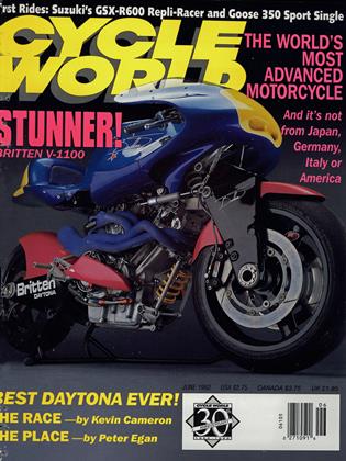
Britten V-1100
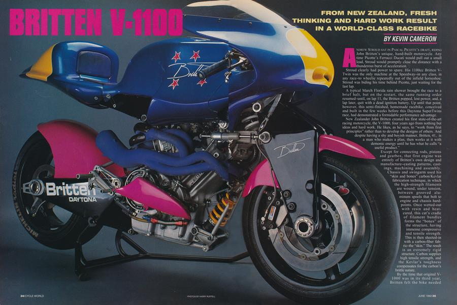
BRITTEN V-1100
FROM NEW ZEALAND, FRESH THINKING AND HARD WORK RESULT IN A WORLD-CLASS RACEBIKE
KEVIN CAMERON
ANDREW STROUD SAT IN PASCAL PICOTTE’S DRAFT, RIDING John Britten’s unique, hand-built motorcycle. Any time Picotte’s Ferracci Ducati would pull out a small lead. Stroud would promptly close the distance with a
thunderous burst of acceleration.
Stroud clearly had power to spare. His 1 lOOcc Britten VTwin was the only machine at the Speedway-in any class, in any race-to wheelie repeatedly out of the infield horseshoe. Stroud was biding his time behind Picotte, just waiting for the last lap.
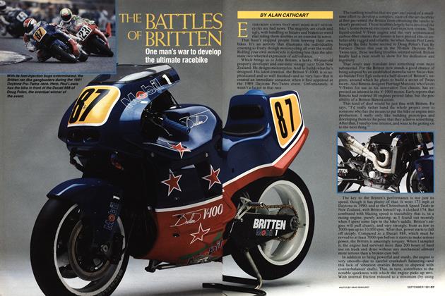
A typical March Florida rain shower brought the race to a brief halt, but on the restart, the same running order resumed-until, on lap 11, the Britten popped, lost power, and, a lap later, quit with a dead ignition battery. Up until that point, however, this semi-finished, homemade racebike, conceived and built in the few weeks before this Daytona SuperTwins race, had demonstrated a formidable performance advantage.
New Zealander John Britten created his first state-of-the-art racing motorcycle, the V-1000, four years ago from nothing but ideas and hard work. He likes, as he says, to “work from first principles” rather than to develop the designs of others. And despite having a shy and boyish manner, Britten, 41. is a man who makes a plan, then works at it with demonic energy until he has what he calls “a useful product.”
V Except for connecting rods, pistons
and gearbox, that first engine was entirely of Britten’s own design and manufacture-casting patterns, castings, machining and assembly. Chassis and swingarm used his “skin and bones” carbon/Kevlar fabrication technique, in which the high-strength filaments are wound, under tension, % between grooved aluminum spools that bolt to \ engine and chassis hard-
! points. Once wetted-out I with resin and heatI cured, this cat's cradle f of filament bundles
1 i forms the “bones” of
the structure, having j, ? immense compressive
and tensile strength. This is then sheeted-in with a carbon-fiber fabric-the “skin.” The result is an extremely rigid structure. Carbon supplies high tensile strength, and the Kevlar’s toughness compensates for the carbon’s brittle nature.
By the time that original V1000 was in its third year, Britten felt the bike needed Omega three-ring piston of amazingly light weight in that size, designed originally for the Judd V-10 Formula One auto racing engine. This bore, with the original 72mm stroke, would give 1108cc of displacement, and with a 64.75mm stroke, a lOOOcc size.
updating. Its longish, 72mm stroke limited its rpm, and the Ducatis that already dominated the class had continually grown stronger. He wanted more than equality.
But where should his effort go? Into a new four-valve cylinder head? Or a five-valve? Or maybe he should develop a novel aerodynamic and cooling concept? Leading-link forks interested him; he felt none seen so far was much good, and he wanted to try ideas of his own. And Marvic mag wheels are expensive; perhaps he could save money and test some ideas by making his own wheels-in carbon fiber.
Any engineer would be proud to succeed in just one of these developments. Indeed, most of those concepts are clearly too much for entire factories, whose output of innovation is in detail improvement, not great leaps forward. John Britten decided to tackle them all: two new cylinderhead designs, fresh aerodynamics, the fork and the wheels.
They all worked.
Near Britten’s house in Christchurch, New Zealand, there is an arrow-straight road about 20 miles long. Here, he had been annoyed to find that last year’s machine, with its sleeklooking full fairing, was actually slower than a previous one with a half-fairing. What could be the reason?
Splitting the wind isn’t the problem, of course. The hard thing is to put it back together-with minimum turbulence and loss-after you have passed. A full-faired machine leaves behind it a large low-pressure area because racing rules don’t permit use of a full, tapering tail that would smoothly close the wake.
Britten’s answer had two parts. One, by eliminating the wide lower fairing, he would reduce the area of the wake. Two, he would fill what wake there was with fast-moving air from two sources. The first source would be air passing between the rider’s calves and the narrow engine-gearbox unit; the second source would be radiator-exit air, delivered from a fully ducted cooling system.
As a result of this approach, Britten’s new racebike is built like a torpedo atop a knife-blade. The torpedo is the windscreen and front fairing, the rider’s body behind it, and the tapering seatback behind that. Below is the blade, consisting of the front and rear tires, plus the narrow engine. Small “boot fairings” provide coverage for the rider’s feet.
Aircraft experience teaches that it costs more power to push air through a resistive radiator core than to flow that same air over the smooth outside of the machine. For lowest drag, then, radiator airflow must be reduced to the least possible. Bike radiators in the conventional position-between the front tire and the engine-work poorly because it’s difficult to eject the heated air into a low-pressure area. Bruteforce methods are used to compensate for this problem; radiators are simply made very large, fed by very large openings. This makes recent racebikes resemble clumsily faired, square-rigged ships. Drag is high.
Britten didn’t want that. So, he located a very small cooler (about 5 by 14 inches) under the rider’s seat, and forced air through it by taking air in at the highest-pressure zone (the front of the fairing) and ducting it back out into the lowestpressure zone (the wake region behind the bike). With this maximum pressure difference across it, supplied through smooth ducting, the horizontal radiator gets adequate airflow at low power cost. Despite its small size, it holds the 1 lOOcc engine at 80 degrees Celcius, or 176 degrees Fahrenheit.
Britten was no less ingenious with the cylinder heads. Despite Yamaha’s inconclusive results with its OX-series of five-valve auto-racing engines, he was intrigued with the extra valve area, which in his own flow-bench testing had delivered impressive amounts of air. First, however, he would develop an improved four-valve cylinder head to work with suitably altered bore/stroke dimensions.
A major source of impaired intake flow in cylinder heads is the masking of valves as a result of their closeness to the cylinder walls. Britten decided to scrap the idea of symmetry in favor of moving the intake valves closer to the roomy middle of the cylinder. This pushed the exhausts, and the sparkplug with them, closer to the front wall. He chose a 99mm bore, partly because he could easily obtain a modem
Because Britten’s resources are limited, he must always find ways to shorten development time-such as he did with the cylinder heads. He cut out an inch-thick plate of dimensions to match the cylinder. Into it he cut dummy valve seats and ports. At each of the cylinder-bolt locations, he placed spacers rising from the plate, serving to define space already needed by the bolts and therefore unavailable for use as port volume. Atop these spacers he located a second plate, into which cylindrical slugs were pressed at his chosen valvestem angles, representing the volume to be taken up by valve guides, spring seats and tappet bores. Each slug was bored to accept a valve stem. In this way, he defined the room left over for the construction of the ports themselves.
With this buck bolted to the flow bench, and with valves in each port, Britten began his port development. First, he measured the airflow of the bare seats with open valves, leading the flow to them with short bell-mouths made of clay. Then he built up the port lengths with clay, adjusting their dimensions as he worked so that no flow was lost as the ports grew longer and longer.
On the intakes, he led the port away from the valve stems at a 13-degree angle. Little by little, he built up the ducts until they reached the planned intake-flange location. He then filled the developed ports with a rubber casting compound to make a male mold, which was then used to make casting molds for the new heads. Aside from sanding to remove casting irregularities, no rework was done on the ports as-cast.
The dyno did not disagree: It said 170 horsepower at 9500 rpm.
Although the previous engine had its intake ports at the backs of the heads (like an H-D dirt-tracker), the new Britten has both intakes repositioned in the Vee so they can be integrated into an airbox. Ram air to this airbox (itself an internal part of the fuel tank) is taken in by a pair of “nostrils” at the front center of the upper fairing.
On the exhaust side, separate pipes emerge from each valve port, bringing four pipes to the collector. The primary tubes are tapered, a design that Britten found no easy way to fabricate; as a consequence, there are 60 hours of work in the exhaust system.
Britten also chose new methods for developing the internal and external shapes of fairing, tank and seat. The basic shape was defined using malleable aluminum welding wire, stuck in place on the mock-up using a hot-melt glue gun. Very quickly, a shape can be developed that resembles the wire-frame models used in computer finite-element analysis; and by bending the wire or relocating the joints, changes can easily be made. Once satisfied with the basic shape, Britten covered the wire frame with a foam that could be carved or sanded after hardening to make a plug on which a female mold was made. The resulting parts are of impressive complexity and smoothness.
Making his own wheels involved Britten first building up a strong hub-and-spoke structure using the previously described “bones” method. The rim was then formed by winding 27 turns of wet-out carbon tape onto this structure. The exact flange and safety-bead contour was defined after resin curing by turning on a lathe. Finally, molded shells were added, one on each side, to integrate the structure.
To measure strength and rigidity, Britten took one of his carbon wheels and a production magnesium wheel to a test center where calibrated loads could be applied and deflections measured. Load for load, Britten’s carbon wheel had only 60 percent of the deflection of the metal wheel. Severe destruction tests followed, and the carbon wheel proved extremely rugged. Satisfied for the moment, he made up five fronts and five rears for use on the new bike.
Creating a new front suspension was more involved. Britten chose the basic girder concept used by Fior and Hossack because of the versatility of its geometry. A pair of leading links projects forward from the front of the bike at steering-head height, each with a ball-joint at its forward end. Attached to thè two ball-joints is a girder, each of whose two legs clamps to an end of the front wheel’s 47mm tubular-aluminum axle. As the wheel and girder rise and fall over bumps, the leading-links rise and fall, and the girder is steerable on the ball-joints. Steering control is through a scissors-link from the girder to a set of handlebars pivoted in the usual location.
For Britten, the big question was, what geometry should he choose? Constant-wheelbase? Zero-dive? Anti-dive?
He rejected all of these-for social reasons. Riders are accustomed to the cues they get from conventional forks which, being set at an angle (the rake), are pro-dive. In other words, some of the braking force serves to compress the fork. The entire feel of a motorcycle entering a comer-its forward pitch and the changes this brings in rake and trail-depends on cues that come from this dive behavior. Take that away, and riders feel uncomfortable at the very least, and possibly in danger.
Britten therefore made his girder fork initially pro-dive, just like a telescopic fork. In the last 1.6 inches of the total 4.7 inches of front-wheel travel, this changes to a somewhat anti-dive behavior. Conceivably, when in the future more is known about the behavior of this type of fork, other geometries may prove to be better, and riders may become accustomed to their “feel.”
Britten experimented on a computer with a linkage program to get the effects he wanted, and found that placement of the leading-link pivots had to be very accurate. Location of the lower pivot subsequently required setting the engine back a half-inch and integrating the pivot point into the engine’s front-cylinder cambox. A conventional nitrogenpressurized spring/damper unit acts on the lower link.
As with the previous bike, rear-suspension forces on the new Britten are carried forward under the engine, via rods and bellcrank, to another spring/damper unit just ahead of the crankcase. The remote reservoirs of both dampers are located on the rider’s “dashboard,” within easy reach for compression-damping adjustment.
During initial testing in New Zealand, riders using the new fork applied brakes at their usual shut-off points, only to have to re-accelerate into most corners because of the shortened braking distance. Unlike a telescopic fork-which becomes jerky and stiff under braking because of the sideloads on its sliding bushings-pivoted-joint suspensions like Britten’s remain supple, and so offer better traction over rough surfaces. Hence the shorter braking distances.
At Daytona, Britten and his crew worked essentially around-the-clock. Not only was the machine almost completely untested, but there were un-looked-for problems. First, intake-valve clearances were disappearing at the rate of .005-inch per 40 laps. While not a threat to the bike’s ability to finish the SuperTwins race, this lash loss was new. Britten thought it might have arisen from his relocation of the fuel injectors to a new position very close to the valves.
Next, water had somehow been lost from the engine during practice, causing a cylinder liner to crack. The crew completely disassembled the engine overnight, brazed the crack, and rebuilt. On top of that, the electronic fuel-injection had a lean spot that hurt acceleration. After the crew downloaded the injection system’s fuel-map program onto their laptop computer and enriched the weak region, the problem was gone.
The three days of practice and qualifying passed quickly and with little sleep. Hampered by the troubles the team had encountered in practice, Stroud qualified on the third row-a disappointing 12th-some 10 seconds slower than Picotte.
But when the final went to the grid and the flag dropped, everything came right as Stroud ran effortlessly with the leader. The Britten had been transformed from a mass of questions into an integrated, powerful answer. The brazed cylinder liner worked. There was no water loss. Handling was good. There remained one unknown defect: During Thursday’s allnighter, a very tired John Britten had installed the small ignition battery incorrectly, so only part of its power served the load, while the rest leaked slowly to ground.
As the race laps passed, Stroud was clearly continuing to test the machine, evaluating how fast he could pull up to Picotte as they approached the chicane. But just as onlookers began preparing for the seemingly certain dramatic finish, the battery expired. The silent Britten rolled to a stop.
Picotte rode well on a fine machine to win the race without further challenge. Britten, Stroud and crew were left with only the glory of all they had dared. And the bright prospect of all they seem destined to achieve. Soon. Very, very soon. □