The Service Department
THE SERVICE DEPARTMENT
JOHN DUNN
SIDECAR SETUP
I am a 54-year-old antique Indian dealer, having sold and serviced Indian motorcycles back in 1936-38 in Quincy, Ill. I now am in the process of restoring a 1940 Indian Four and sidecar outfit. I have many back issues of your fine magazine as I try to keep up with the sport I loved during my youth.
I came across your January 1967 issue in which you had three sidecar features. One feature titled “All About Sidecar Racing” contained this statement: It is usual to make the sidecar wheel toe in, an absolutely essential factor for a road outfit which needs 1.25 to 2 in. toe-in.
I would like to know how this is determined and where to measure to be accurate. Please explain this point to an old wooden Indian.
H.E. Weber
Quincy, Ill.
There are no hard and fast rules on the amount of toe-in that will be required. A light sidecar may need anywhere from 0.5 to 1.0 in., while a heavy rig may need as much as 1.5 in. Other factors influence the best compromise, such as position of sidecar wheel in relation to wheelbase, weight distribution, suspension characteristics and machine lean-out. If you already have a sidecar, you may be limited with respect to the position of the sidecar wheel. Ideally, the sidecar wheel axle should be between 6 and 10 in. in front of the rear wheel axle. Once this has been fixed, the two most important adjustments and subsequent settings are sidecar wheel toe-in and machine lean-out. I suggest you start out with 1.0-in. toe-in and 1.0-in. machine lean-out and proceed in the following manner.
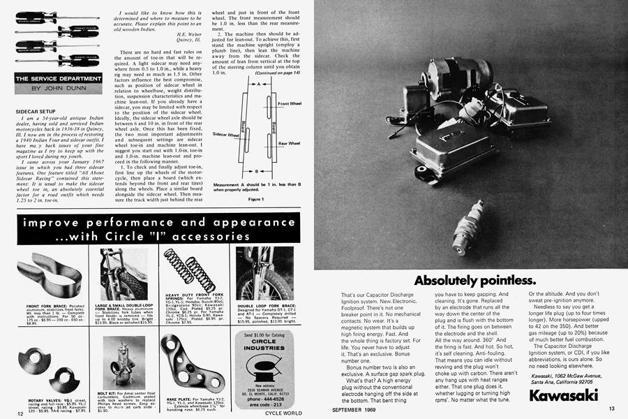
1. To check and finally adjust toe-in, first line up the wheels of the motorcycle, then place a board (which extends beyond the front and rear tires) along the wheels. Place a similar board alongside the sidecar wheel. Then measure the track width just behind the rear wheel and just in front of the front wheel. The front measurement should be 1.0 in. less than the rear measurement.
2. The machine then should be adjusted for lean-out. To achieve this, first stand the machine upright (employ a plumb line), then lean the machine away from the sidecar. Check the amount of lean from vertical at the top of the steering column until you obtain 1.0 in. (Continued on page 14)
Continued from page 12
Figure 2
HALF-HEARTED HONDA
My 450 Honda Scrambler has 1100 miles on it. At 332 miles, the compression was 155 lb. and 165 lb. on the right and left cylinders, respectively. Now it has 120 lb. in each cylinder. Putting oil in the cylinders brings the compression up to 210 lb. in each cylinder.
The factory service manual says that the compression should be 165 lb. Acceleration is good, although it will only pull 8000 rpm in high gear. I use SAE 20-40 oil in the machine, and timing is right on, using a strobe light. Also, I use NGK B9E spark plugs.
Phil Scott Lodi, Calif.
The performance of your 450 Honda certainly appears to be below par. The minimum acceptable cylinder compression pressure should be 150 psi. A compression pressure of 170 psi should be considered maximum. Compression pressure should be checked with a hot engine, the throttle and choke wide open, and the engine vigorously turned over by means of the kick starter until the compression gauge indicates maximum pressure. Also, check that the air cleaners are not choked. A low compression indicates a high level of leakage from the combustion chamber, either past the piston rings, by poorly seating valves or a leaking gasket. You cannot see all of the cylinder wall through the spark plug hole, particularly the heavily loaded thrust face where trouble is most likely to occur. It will be necessary to dismantle the engine to check the condition of the cylinder walls, valve seats (check for bent valves) and gaskets.
(Continued on page 18)
Continued from page 14
The performance of your machine indicates that the mixture is on the lean side or that the spark plug is too warm. After you have inspected the engine, try a 135 main jet and a B10 grade of spark plug.
SUZUKI CIRCUITRY
When setting the timing on my 1967 Suzuki X6, I use a light and separate battery source across the points so that when the points close the light will burn. However, the light still glows dimly when the points are open and brightens when they close. On my brother’s ’68 X6, the light does not glow at all until the points close. My bike starts and runs well, but this difference makes me think that the condensers might be faulty. The points don’t last as long as they should either (2000 miles).
Thomas Griebe Rochester, Mich.
In a simple circuit, the test light should go out when the contact points are open (Fig. 1). However, some electrical systems have circuits connected to the dead side (ignition switch off) of the ignition switch, which in some cases are grounded (Fig. 2). When you connect your test light and separate battery in series, a circuit is grounded through the additional system. If the resistance of the circuit, which includes the resistance of the primary side of the high tension coil, is high, the test light will glow. If the resistance is low, the test light will light fully.
(Continued on page 22)
Continued from page 18
I am not conversant with all the possible wiring variations that may have been made to the Suzuki X6. There may be some differences between yours and your brother’s machines that cause the test light to glow on yours but not on his. It is doubtful that leakage of the condensor would be causing the difference. If the condensor had a leakage rate high enough to cause this, the points would burn out long before 2000 miles had been covered. Short point life often is the result of installing the points without first cleaning off the protective coating from the point face.
DARKNESS, DARKNESS
I own a 1968 Bridgestone 350 GTR. My problem is the electrics on my machine. I cannot run the bike with the lights on at night. When I turn the switch for the lights, the engine cuts completely. I’ve replaced the battery, but it was drained of power after about 10 miles of riding and being left to sit overnight. I’ve checked the wiring and everything seems to be in order. Also, a new ignition switch was installed but that didn’t help.
Craig P. Gindele
Riverside, Calif.
It appears that the problem is the generator. Just a small portion of the generator is used for daylight operation, with current sufficient only for ignition purposes. When the lights are switched on, the major portion of the generator is brought into operation, supplying additional current. If the lighting coils in the generator are defective, there would be no additional output for lighting demands. This would rob the ignition system of current causing it to misfire or even cut out. I suggest you have the output of all the generator coils checked by a competent dealer.