Understanding Electronic Ignition
understanding electronic ignition
A Technical Exploration Of The Important New Advances In Ignition Theory.
BY T.E. INGERSON
AN INTERESTING DEVELOPMENT in the field of engine design during the past few years has been the appearance of electronic ignition systems. These are often called "transistorized." However, some of them do not utilize transistors, so the term is unnecessarily restrictive.
Application of these systems to motorcycle ignition has come more slowly than to automobiles. It is only in the past year or two that electronic motorcycle ignition has made a significant appearance, in the design of new engines, or available as a modification to existing engines. Since electronic ignition systems have characteristics which are often peculiarly applicable to the particular needs of motorcycles, they should be understood by every serious motorcyclist.
It is the intention of this article to describe their characteristics, their application to motorcycle design, and the types and reasons for use. It is not intended as an aid to construction of electronic ignition, but to understanding. The circuits illustrated in this article are examples only and will not necessarily work properly as shown, nor are values worked out for construction.
PRELUDE: BASIC IGNITION THEORY
First, a bit of terminology for the person unacquainted with electricity. Voltage refers to the "pressure" of an electrical charge. If two electrodes are separated by some distance, and are given a voltage difference, electrons are pulled from one electrode towards the other with a force which increases as the voltage difference increases, and decreases as the distance increases. Eventually, as the voltage is increased, the air will ionize (the atoms will separate into nuclei and electrons), and then electric "current" will flow. The term "current" refers to the movement of an electric charge from one electrode to another.
In an internal combustion engine ignition system, there is generated across the gap of the spark plug at the instant of ignition a very quick rise of voltage which causes ionic movement. When the voltage reaches a sufficient value, the gap breaks down, current flows, and the moving charges in the gap heat the atoms within the gap, creating a hot, electrically charged plasma which ignites the compressed gasoline-air mixture in the cylinder.
Somewhere in the ignition system is stored a quantity of electricity which provides the energy for spark. The more energy, the hotter the spark. When this energy is exhausted, the spark fades, the ignition system prepares for the next spark, and the gasoline in the cylinder presumably is burning.
Always, whether the ignition system is conventional or electronic, the spark is generated by means of a spark coil, which operates on the following principle: Whenever a changing magnetic field is introduced within a coil of wire, there is induced in the coil a voltage proportional to the rate of change of the magnetic field within the coil." The faster the magnetic field changes, the more voltage will be induced (though for a proportionately shorter time, of course). Because current flowing in a coil of wire produces a magnetic field, we could take two coils of wire, wind one on top of the other, change the magnetic field rapidly in one by interrupting or alternating the current rapidly, and produce a very large voltage in the other. This is precisely what a spark coil is.
The two coils are referred to as the primary and the secondary, and one wire from each coil is generally connected to a common terminal so that the spark coil has only three leads. However, this is done for mechanical convenience rather than for theoretical reasons. The coil in which the voltage is induced (called the secondary) has many more turns than the coil which produces the field (the primary) in order to obtain the maximum voltage. There is an optimum in the difference in size of the two coils, for after the voltage induced is high enough to produce a breakdown and current flow in the spark gap, little purpose is served in having a very much higher voltage. Some excess is necessary to allow for the insulation value of oil and corrosion which may have collected on the spark plug.
One lead of the secondary coil goes to the spark plug, one lead of the primary to the ignition system, and one lead of each is generally connected to the frame of the motorcycle. (Often the latter is referred to by the misleading term "ground," to which there is no connection.) The problem of the ignition system is to produce a rapidly changing magnetic field in the primary coil. Now we will see how this is done in both conventional and electronic systems.
Some things are common to all ignition systems: A spark coil, as already mentioned; an interrupter for producing a rapidly changing magnetic field in the primary coil at the proper time; and a device for storing energy for the spark. Producing a spark accomplishes nothing if there is not enough energy behind it to adequately heat the air in the gap.
CONVENTIONAL IGNITION SYSTEMS
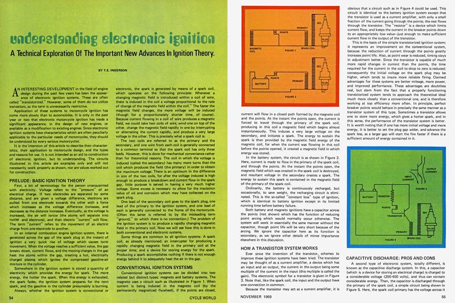
Conventional ignition systems can be divided into two related but distinct types: magneto and battery systems. The magneto uses a circuit such as illustrated in Figure 1. When current is being induced in the magneto coil (by the permanently magnetized flywheel), if the points are closed, current will flow in a closed path formed by the magneto coil and the points. At the instant the points open, the current is forced to travel through the primary of the spark coil, producing in this coil a magnetic field which begins almost instantaneously. This induces a very large voltage on the secondary, and initiates a spark. The energy to sustain the spark is theh provided by the magnetic field energy of the magneto coil, for when the current was flowing in this coil before the points opened, it created a magnetic field in which energy was stored.
In the battery system, the circuit is as shown in Figure 2. Here, current is made to flow in the primary of the spark coil, and through the points. At the instant the points open, the magnetic field which was created in the spark coil is destroyed, and resultant voltage in the secondary creates a spark. The energy to sustain this spark is contained in the magnetic field of the primary of the spark coil.
Ordinarily, the battery is continuously recharged, but occasionally, to save weight, the recharging circuit is eliminated. This is the so-called "constant loss" type of ignition, which is identical to battery ignition except in its limited running time before battery failure.
Both battery and magneto ignitions have a capacitor across the points (not shown) which has the function of reducing point arcing which would normally occur otherwise. The system will work in essentially the same manner without the capacitor, though point life will be very short because of the arcing. We ignore the capacitor here as its function is secondary, as we ignore other details of minor importance elsewhere in this discussion.
HOW A TRANSISTOR SYSTEM WORKS
Ever since the invention of the transistor, schemes to improve these ignition systems have been tried. The transistor may be thought of as a current amplifier, a device which has an input and an output, the current in the output being some multiple of the current in the input (this multiple is called the gain). The electronic symbol for a transistor is given in Figure 3. Note that, like the spark coil, the input and the output have one connection in common.
Because the transistor may act as a current amplifier, it is obvious that a circuit such as in Figure 4 could be used. This circuit is identical to the battery ignition system except that the transistor is used as a current amplifier, with only a small fraction of the current going through the points; the rest flows through the transistor. The "resistor" is a device which limits current flow, and keeps the current in the breaker points down to an appropriately low value—just enough to make sufficient current flow in the output of the transistor.
This is the basis of the simple transistorized ignition system; it represents an improvement on the conventional system, because the reduction of current through the points greatly increases point life. Also, as point wear is reduced, timing stays in adjustment better. Since the transistor is capable of much more rapid changes in current than the points, the time required for the current in the coil to drop to zero is reduced; consequently the initial voltage on the spark plug may be higher, which tends to insure more reliable firing. Claimed advantages for these systems are better mileage, more power, and improved performance. These advantages are doubtless real, but stem from the fact that a properly functioning transistorized system tends to approach the theoretical ideal much more closely than a conventional one, and is therefore working at top efficiency more often. In principle, perfect breaker points would behave in precisely the same manner as a transistor system of this type. Sometimes a transistor allows one to store more energy, which gives a hotter spark, and in this sense, the performance of the transistor system is better. It is worth noting that if one has more initial voltage and more energy, it is better to set the plug gap wider, and advance the spark less, as a larger gap will start the fire faster if there is a sufficient amount of energy contained in it.
CAPACITIVE DISCHARGE: PROS AND CONS
A second type of electronic system, totally different, is known as the capacitive discharge system. In this, a capacitor (which is a device for storing an electrical charge) is charged to a considerable voltage (200-400 volts), and thus can contain considerable energy. Then, the capacitor is discharged through the primary of the spark coil, a simple circuit being shown in Figure 5. Here, the spark coil primary has the voltage across it raised to a very high value at the instant the points close, which induces a spark, the energy in the spark coming from the energy stored in the capacitor. The stored energy may be as large as desired, limited only by what its 200-400 volt power source can deliver. This system works very nicely, but is limited by the fact that, in an engine, no simple source (i.e., a lightweight, rechargeable battery) of anything but 6 or 12 volts exists, so a device must be built which produces the charging voltage. This is expensive and complex, so capacitive discharge is generally used only on higher priced electronic ignitions. The high voltage must be generated with a transistor oscillator which changes the 6 or 12 volts direct current to alternating current, passes it through a transformer which increases the voltage to 200-400 volts and then changes the a.c. back to d.c.
Capacitive discharge produces an excellent ignition system, with quick induction of a very high spark plug voltage, as well as the ability in principle to put as much energy as desired in the capacitor. These systems are reputed to give significant improvement in performance when properly designed.
Capacitive discharge fires when the points close, rather than when they open, as with the other systems. This is no great problem, for electrically it is not difficult to adjust the circuit so that when the points open, the effect on the capacitor will be as if they closed. With a transistor playing the role of the points in Figure 5, the points carry very little current. Most will go through the transistor, which will keep point life high, as well as guaranteeing that the capacitor will discharge with the very short time characteristic of the transistor. A simplified circuit is illustrated in Figure 6. The points, when closed, force all the current through the resistor to go directly to point A, allowing nothing to go through the input of the transistor. When the points open, the current which was passing through them goes through the transistor, suddenly discharging the capacitor.
SILICON CONTROLLED RECTIFIER
Another device which is very commonly used for this purpose is the so-called "Silicon Controlled Rectifier" (SCR). The SCR operates much like the transistor in that it is a current amplifier (though with a much higher gain). But once a current is initiated in an SCR, it continues without stopping until no more current is available to go through it. The electronic symbol for an SCR is shown in Figure 7. When a small trigger current turns it on, current flows in the main circuit, even if the trigger pulse is then shut off.
The SCR lends itself perfectly to the requirements of a capacitive discharge system. It replaces the transistor in Figure 6 and, once triggered, will suddenly drain the capacitor of its charge. Once this charge is drained, the SCR will cease to conduct, and the capacitor will recharge for the next pulse.
The SCR also lends itself to another interesting approach to e ectronic circuitry. Obviously, elimination of the points in any ignition system would be an advantage. As moving parts, the points undergo mechanical wear, and are subject to misadjustment and to inaccurate opening and closing time at high rpm when the points must open and close faster than mechanical devices can easily function.
Two systems are commonly used to do away with the points.
One requires a photocell (a light-sensitive cell which generates a small current when light hits it), a light source and a small hole or notch on the flywheel to allow the light to pass through to the photocell at appropriate intervals. As the light hits the photocell, a signal is generated which may be used to trigger the SCR.
The other "pointless" scheme utilizes a small trigger coil and a magnet on the flywheel. When the magnet passes by the coil, it induces a current in the small coil to trigger the SCR.
Both methods work well, and have been used, though not extensively. This is mainly because they involve internal modification of the engine (flywheels being characteristically inaccessible), and because in multiple cyclinder engines, they cannot eliminate the other moving part in the system, the distributor rotor. At present it is not within the state of the art to have transistors switch the ignition voltage from cylinder to cylinder. In order to dispense with moving parts entirely, one must have as many capacitive discharge ignitions as one has cylinders, which is usually uneconomical, and therefore seldom used.
Also, the automatic spark advance mechanism is usually associated with the points. If one wishes to go to photocell or trigger coil discharge systems, one must devise some sort of electronic spark advance, which, while relatively simple electronically, serves merely to increase the complexity of the ignition, and is consequently looked on with disfavor.
BOLT-ON ELECTRONIC IGNITION
The majority of commercial "bolt-on" electronic ignition systems for either cars or motorcycles are of the simple transistor amplification type, and can be easily installed. The user simply disconnects the conventional connections to the points, and allows the transistor to carry the bulk of the current. There exist commercial capacitive discharge systems which also bolt on, and contain a high voltage power supply, a capacitor and usually an SCR to discharge the capacitor.
(Continued on page 82)
Continued from page 56
It is only necessary to disconnect the wire leading to the points, and reconnect a wire going to the new ignition system, as well as connecting a wire from the spark coil to the ignition system. Commercial devices involve a minimum of effort, and once installed should give more reliable ignition, somewhat of an improvement in performance and a reduction of fouling, less maintenance, and a generally significant (though usually not spectacular) improvement in overall ignition system performance. For the motorcyclist, these systems may well be worthy of consideration, though their weight and bulk may deter some people. Though they are not terribly large or heavy, when every pound counts in a racing bike, a nonessential pound may be looked on with dismay. Twin-cylinder, two-coil engines still require two ignition systems, which makes the bite out of the pocketbook even less attractive.
The prospect of incorporating electronic systems in designs of original equipment is quite appealing. Consider a magneto system; if a small secondary trigger coil is wound around a magneto coil, and then used to trigger an SCR, one obtains electronic ignition with only the winding of a different type of magneto coil, and the addition of two parts—a capacitor and an SCR (plus some minor parts). These parts are not very expensive or very large, so one may have electronic ignition at virtually no cost in terms of money or bulk.
THE ADVANTAGES OF THE DIODE
A third new part is required in order to take full advantage of a magneto capacitive discharge system. Its use may be understood by recalling that a magneto generates first a positive, then a negative, then a positive, voltage, as the north, then the south, then north poles of the flywheel magnets pass by the coils. If one wishes discharge to occur on one of these voltage generations, it is best to charge the capacitor on the previous generation so that the capacitor can have as much time as possible to charge. This requires that a diode be placed in the circuit, as in Figure 8. A diode is a device which conducts electricity only in one direction. This means that if the diode is placed correctly, when the magneto generates a positive voltage, the diode will allow the magneto to charge the capacitor with a positive voltage. But when the voltage generated by the magneto becomes negative, the diode will not permit the capacitor to discharge through the magneto, and charge negatively, as it would were the diode not there. With the diode in the circuit, the capacitor may be charged on one pulse of the magneto, and the trigger coil wound so as to discharge the SCR on the next pulse. By simply winding the trigger coil in the opposite direction from the magneto coil, or reversing the trigger coil wires, a pulse of the appropriate polarity will be sent to trigger the SCR on the opposite magneto pulses from the ones used to charge the capacitor. The capacitor will be fully charged when the SCR is fired.
This system also has the advantage of an automatic spark advance effect; since the voltage generated by the trigger coil is increased by the speed of the engine, the SCR will reach critical firing voltage earlier if the engine is running faster, and serve to advance the spark.
This system is coming into use. Ossa and Bultaco use such an ignition method. Its superiority is such that within a few years, it very likely will become all but universal on magnetopowered bikes (except for small machines where cost may be prohibitive). Its advantages are significant, especially in the improvement in low end torque because of the spark advance, and the reduction of fouling because of the higher voltage and greater spark energy. This should especially appeal to the manufacturers of two-stroke engines.
Characteristic of electronic systems is that they work magnificently unless something is nonfunctional. When solid-state electronic devices are inoperative, they usually exhibit not the slightest sign of life, as opposed to mechanical devices which work even when they are thinking about breaking. However, electronic devices, when properly designed, literally last forever, and should therefore greatly increase reliability and decrease maintenance.
This is the state of electronic ignition today. Though electronics has had a slow start in the motorcycle business, it is catching on. Motorcycles may find themselves the first segment of the engine industry which converts largely to electronics. m