Turn Signals
TURN SIGNALS
A FLASHY HOW-TO CONVERSION.
JACK WILLIAMS
RIDING MOTORCYCLES in heavy traffic can present many problems. Joe Whatsis, with his heap of Detroit iron, isn't about to give you a break. Probably the best way you could impress him with the fact that bike riders also have a right to be on the road would be to take a hammer, walk up to his car, and while you are beating him on the head, inform him that you are about to turn the next corner and that you would appreciate his cooperation. Pleasant as this may be to contemplate, it just isn't done in the best circles.
There has to be a better way! You could hold out your hand every time you want to make a turn but that necessitates one of two alternatives. Either you put your hand back on the handlebars before you turn, giving Joe the chance to say he thought you had changed your mind about turning, or, you can sail around the corner with your hand sticking out like a mail hook picking up the mail. This certainly will inform Joe that you are turning but it will leave you with the problem of how to work the front brake on a right turn or the clutch on a left. Neither of these alternatives is very attractive. Is there a satisfactory answer? Ah, yes. Turn signals. For the magnificent sum of $10.00 or less, depending on your ingenuity, you can have your bike equipped with a sharp set of turn signals. Blinker lights, two amber for the front and two red for the rear, can be purchased from the local discount store, auto parts or hardware store. The common name for these are "clearance lights." They will cost you around 50 cents each.
If you can fit 21 candle power bulbs into your lights so much the better but most clearance lights will only take a 15 CP (candle power) bulb. The larger bulbs hit the plastic lenses and will melt them. Sometimes you can save a little money by trading the 3 CP bulbs that you get with the lights for the larger 15 CP bulbs. If your bike is a 6-volt machine, get 6-volt bulbs. If it is a 12-volt system, you will obviously need the 12-volt bulbs.
You will also need a switch for indicating the direction you are going to turn. A handy choice is a Shurhit # S213, used for switching from the front speaker to the rear speaker in your car. The hose clamp is mounted on the handlebars to hold the switch.
The next part is the flasher unit. This is a flasher unit from an automobile turn signal system. You can buy these units for about $1.85, complete with the mounting bracket. It is best to buy the type with screw lugs. Try and get one that will actuate on two 15 CP bulbs and be sure to get the correct voltage for your bike.
All that remains on the list is the wire for hooking up the system. Number 16 or 18 wire can be used. It should be the flexible rubber-covered kind and you will need about 15 feet. This wire can be bought for 3 cents a foot almost anywhere.
Also necessary to complete the installation is the bar for spacing the rear turn signals so that someone behind you can tell if you are going to turn right or left. Any piece of metal about 1/8 of an inch thick, 1 inch wide, and about a foot long will do the job.
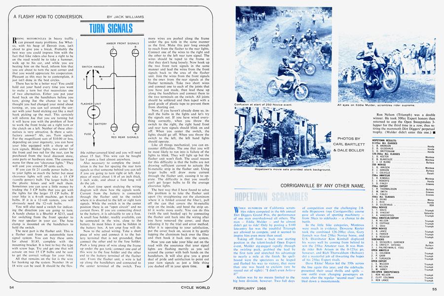
A short time spent studying the wiring diagram will show how the signals work. Current from the battery is connected through the flasher unit to the switch where it is diverted to the left or right turn signals. While the switch is in the center position there is an "open circuit" and no current flows. If you are connecting direct to the battery, it is advisable to use a fuse. A small fuse holder, readily available, can be connected in the wire, close to the battery. In most bikes it can be hidden in the battery box. A ten amp fuse will do.
Now to the actual wiring. Take a short piece of wire and connect it to the battery terminal that is not grounded, then connect the other end to the fuse holder. Push a long piece of wire along the frame up under the gas tank; connect one end of this wire to the fuse holder and the other end to the battery terminal of the flasher unit. From the flasher unit, a wire is led up along the handlebars and connected to the center terminal of the switch. Two more wires are pushed along the frame under the gas tank in the same manner as the first. Make this pair long enough to reach from the flasher to the rear lights. Connect one of the wires to the right and the other to the left rear turn signal. The wires should be taped to the frame so that they don't hang loosely. Now hook up the two front turn signals in the same manner and lead the wires from the front signals back to the area of the flasher unit. Join the wires from the front signals to the ones from the rear signals at the flasher terminals. Take two short wires and connect one to each of the joints that you have just made, then lead these up along the handlebars and connect them to the two terminals on the switch. All joints should be soldered and then taped with a good grade of plastic tape to prevent them from shorting out.
Now, if you haven't already done so, install the bulbs in the lights and let's try the signals out. If you have wired everything correctly, when you throw the switch to the right, the right hand front and rear turn signals should blink on and off. When you center the switch, the lights should go off. When you throw the switch to the left, the left hand lights should operate.
Like all things mechanical, you can encounter difficulties. The one that you will be most likely to run into is failure of the lights to blink. They will light up but the flasher unit won't flash. The usual reason for this difficulty is that the bulbs are not drawing sufficient current to actuate the bi-metallic strip in the flasher unit. Using larger bulbs will draw more current through the flasher unit, causing it to operate. The difficulty is that you usually can't get larger bulbs to fit the average clearance lights.
The best way that I have found to solve this problem is to take the flasher unit apart (by straightening out the aluminum where it is folded around the fiber), pull off the can that covers the bi-metallic strip on the inside, and bend the strip until it works more easily. You can do this (with the unit hooked up) by connecting the flasher unit back into the wiring after you have removed the cover, and then adjusting it by the trial and error method. After it is operating to your satisfaction, put the cover back on, secure it by gently tapping the aluminum back over the fiber and then hook it back into the system.
Now you can take your bike out on the road with the assurance that your signal lights are flashing merrily as you sail around the corner with both hands on the handlebars. It will also give you a great deal of pride and satisfaction to point out your turn signals as just a little thing you dashed off in your spare time.