Technical Analysis: Matchless G-50 Engine
TECHNICAL ANALYSIS: MATCHLESS G-50 ENGINE
The power plant for the G-50 and G-50 CSR, an excellent example of the fine British art of single-cylinder racing engine design.
THROUGHOUT the world, it is customary for manufacturers to build single- or twin-cylinder engines to power the machines they sell for general road work, and to go on to more cylinders for their racing motorcycles. Fours, sixes, and even one V-8 has been turned out for Grand Prix racing — but they have almost never been offered to the general public.
In England, however, this order of things is com pletely reversed; they turn out twins by the carload for touring motorcycles, and have even built a few fours for mass-sales, but when they go racing, they inevitably seem to revert to the single-cylinder layout. One reason for this may be that their multi's have almost always been a disappointment, while they are the acknowledged past-masters of the single-cylinder art. No one gets more power, torque, smoothness or reliability out of the big "banger" than the British. Tn fact, if the builders of those spectacular multi's had the English designer's infinite capacity for attention to detail, their creations would he even faster than they are
One builder of racing multi's, Honda, seems to have acquired this knack over the past couple of seasons of racing and the results speak for themselves. However, the lessons are more easily learned with a single, there being fewer parts to confuse the issue, and the best "text book" available is the English racing engine, of which the Matchless G-50, presented here, is a superb example.
As a design, the G-50 is almost an exact copy of AMC's AJS 7R, which was introduced in 1948. The 7R, which is still very much in the picture, has the same stroke, 3.07 inches, and a bore of 2.972 inches, giving a displacement of 21.35 cubic inches, or 348 cubic centimeters. For the G-50, a new cylinder and piston were fitted (and some minor revisions were made to the cylinder head and crankcase) to give a bore of 3.54 in. and a displacement of 30.25 Cu. in., or 4Q,c('r
In assessing the 7R/G-50 design. it should be understood that it was designed for production from the first, and while the original design specifications in cluded those features that give a high power output, it was considered equally important that a high decree of reliability be retained. Moreover, it was essential that the design be simple enough so that the private owner, for whom it was intended, would be able to maintain it without elaborate facilities or undue expense. A tall order? Yes indeed, but as the years have demonstrated, they did very well.
BY GORDON H. JENNINGS
Initially, it was appreciated that no matter how clev erly the upper end of the engine was designed, it would all go for nothing if the crankshaft could not carry the load. Accordingly, every effort has been made to provide strength in that area. The flywheels are forged from nickel-chrome molybdenum steel and are joined by a two-piece crankpin. This has a straight-through section,
with threaded ends, and a hardened collar that is the inner bearing race. The through section is drilled to feed oil to an annular groove inside the collar and oil is fed to the rod bearing via a pair of holes in the collar itself. Rigidity is supplied by pulling the flywheels to gether against the sides of the bearing-race collar by tightening nuts on the threaded ends of the crankpin. The mainshafts are flanged on their inner ends and are an interference fit. Their flanged end fits into a recess in the center of the flywheel and the space
consuming securing nut is eliminated. The width of all bearings, shafts and the flywheels is held to a minimum to reduce the span between main bearings and insure maximum rigidity. The lengths to which the designers have gone may be judged by the odd crankpin fastening nuts used. These have an extended cylindrical section that fits into recesses in the outer sides of the flywheels and the hexagonal portion, to which the wrench is fitted. stands free. After tightening, this hexagonal head is sawed away, leaving only enough of the narrowed end of the nut to hold the flywheel. This system has the ad vantage of saving space and has been completely suc cessful - although it is necessary to break away the nut in pieces and fit new ones when the engine's lower end is overhauled.
The crankcase of the G-50 is quite narrow, and is cast from a magnesium-aluminum alloy. Like most crankcases of this type, it is split on its centerline and forms both crankcase and oil sump for the engine. Unlike the others, though, the casing is not extended to contain the ignition and camshaft drives. These are carried in a separate casting bolted on the “right” side of the engine.
The drive to the single overhead camshaft is an interesting bit of machinery. A set of 2:1 reduction gears take the drive from the crankshaft and from this gearset a single-stage chain drive leads up to the cylinder head.
This is very unusual in a racing engine; gear-train or bevel-gear and tower shaft drives are the conventional methods used. However, due to the reduction gearing, the G-50’s cam-drive chain is only running at 1/2 engine speed and the arrangement has been giving good results for approximately 14 years. One reason for this may be that the designers have taken such pains to see that there will be no chain flutter. A spring-loaded, blade-type tensioner runs against the slack side of the chain and this has a friction damper at its free end to stop the vibrations caused by “feedback” from the cams. A rub-strip opposite the tensioner rides against the chain and it, too, serves to dampen-out chain flutter.
One might logically ask why, with the need for all
of this tensioning and damping, chain drive was selected at all? There are several reasons. First, an all gear drive was eliminated because it is so difficult to maintain a proper mesh with all of the expanding and contracting of an aluminum alloy engine, and the spur gears used in such a drive tend to be very noisy even when in proper mesh.
Secondly, the tower shaft arrangement was decided against because of the extreme precision with which such drives must be constructed. All that was left was the chain, which is relatively cheap, quiet (if‘that counts for anything) and insensitive to small changes in oncenter distances.
Thus, in the G-50 engine, it is possible to change the compression ratio by simply stuffing spacers of different thicknesses under the cylinder. This would, of course, not be possible with an all-gear drive and the towershaft layout would require a lot of adjusting with the changes in cylinder height.
A final comment on the camshaft drive: by juggling a series of keyways, sprockets and drive-pins, the valve timing may be brought to within 0.5° of the “exact” setting.
Contained with the same casing as the camshaft drive are the oil pumps and the magneto drive. There is a gear train out to the magneto and it, like the camshaft, can be jiggled one degree at a time. The idler gears that take the drive from the crankshaft to the magneto also serve to drive the oil pumps. Two entirely separate gear-type pumps are used — one for pressure feed to the engine, the other scavenging oil from the sump, it is more common to have both pressure and scavenging pumps combined in a single housing, but this makes the pump longer and, in the G-50, it would have necessitated a lump on the side of the engine. It is, naturally, best if a racing engine can be kept narrow and that is the reason for the two pumps.
In the cylinder head, a single, centrally-positioned camshaft operates both valves. Forged steel rockers carry the motion from the cams to the valves, and there are .75-in. rollers in the cam follower end of each rocker. Early engines had pad-type followers, but these proved to be somewhat sensitive to lubrication interruptions and the change was made. The roller is a trifle heavier, but has been 100% reliable — and that is what matters most at Matchless. A nice, if not unusual, touch was the method provided for valve clearance adjustments: instead of having screw-type adjusters, each rocker pivots on an eccentric bushing, and these bushings can be turned to set the clearance.
The valves are set into the hemispherical combustion chamber with an approximately 75% included angle, with the exhaust valve tilted over a trifle more than the intake. The intake port has a pronounced “downdraft” angle and is bent around to the side at about 20%, this angle provided to give a swirl to the inrushing fuel/air charge.
For the G-50 CSR, the G-50 engine has been detuned somewhat — although not so much that it is exactly gentle. The only difference worth mentioning is the carburetor: a throat size of 1-1/2 in. is specified for the road racing G-50, and this has been reduced to 1-3/8 for the “street” model. The carburetor is, in both cases, a great fierce-looking GP-series Amal, with a remote needle and the new-type, narrow remote float chamber.
In either state of tune, some power at the top end has been sacrificed for good torque and power over a broad range, and we think perhaps they just may have the right idea. Very highly tuned engines require fiveor six-speed close-ratio transmissions, and on some courses a rider can spend so much time stirring the gears about that he loses any advantage that the extra power might otherwise have given him.
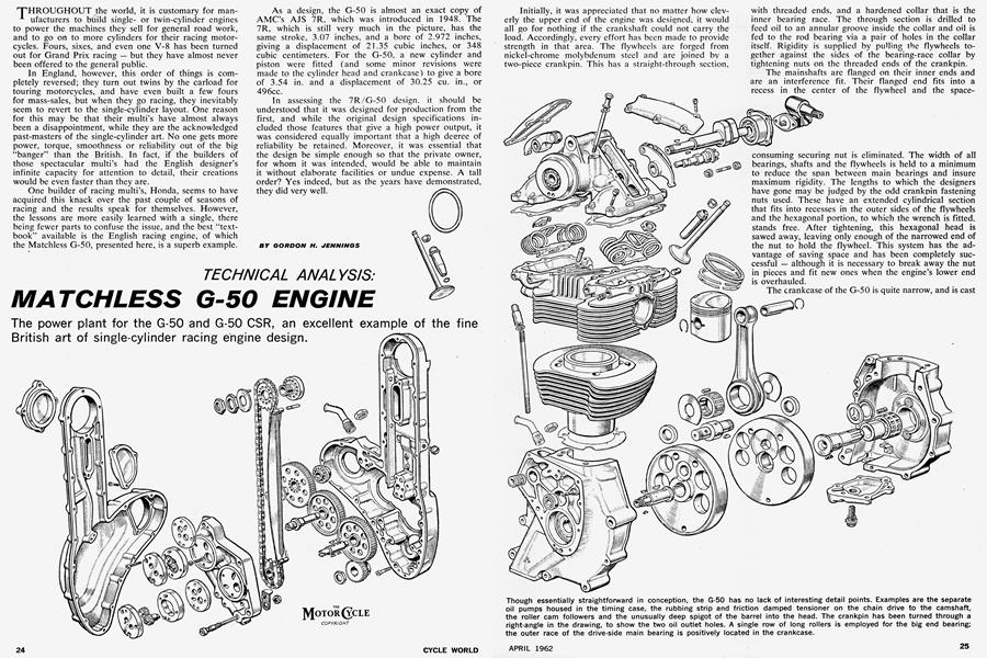
Mostly, the things that make the G-50 engine a good design are its flexibility, reliability, and the fact that it is easy to keep in good repair. These things are essential for the private owner, and the G-50’s successes have been because it supplies these things in large measure. •